Teledyne API Model 401 O
3
Photometric Calibrator Instruction Manual, 01124, Rev. J2
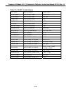
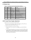
8.7 Status Lines
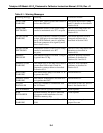
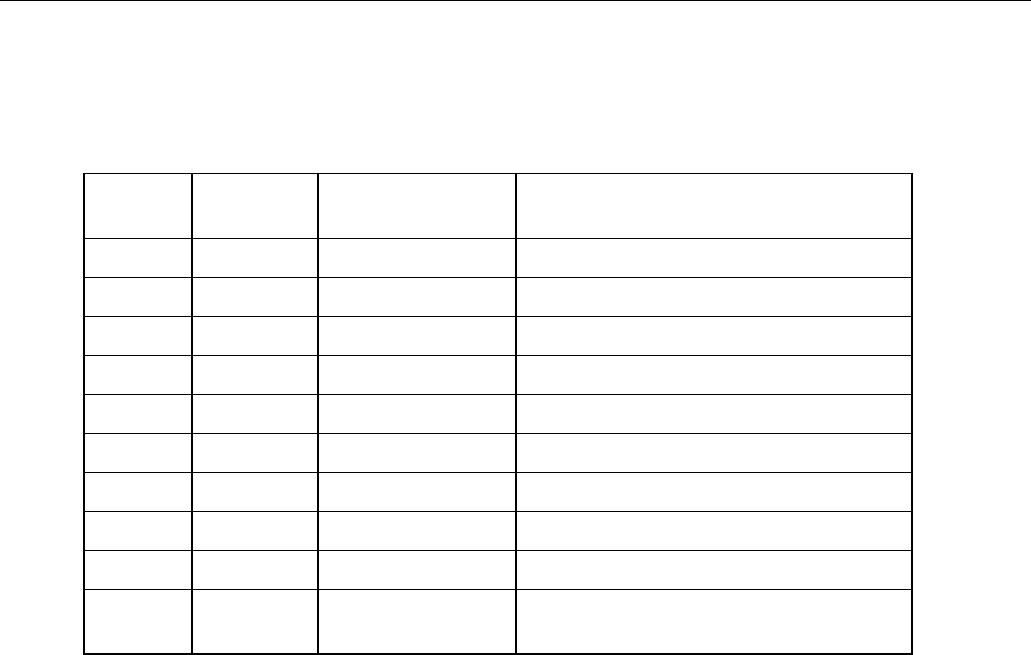
Table 8-1: The Calibrator Has The Following Status Conditions
Output #
Pin Pair
High/Low
Status Condition
1 1, 2 ZERO CAL In Zero Calibrate
2 3, 4 SPAN CAL In Span Calibrate
3 5, 6 FLOW ALARM Flow Warning
4 7, 8 TEMP ALARM Any Temp Warning
5 9, 10 DIAG MODE In Diagnostic Mode
6 11,12 POWER On As Long As M401 Is Running
7 13,14 PRESS ALARM Alarms On Low Pressure
8 15,16 IZS FLOW Warn Alarms If No IZS Flow
9 17,18 SYSTEM OK Alarms If Any Fault Is Present
10 19,20 LAMP WARNING
Alarms If The Calibrator Lamp Intensity
Is Out Of Limits
8.8 UV Lamp Power Supply Adjustment
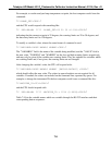
Adjust the drive power of the lamp power supply as follows:
1. Remove the cover of the lamp power supply. Attach a DVM across TP7 and TP10, and
adjust the pot (VR1) until the DVM reads 20 volts
± 1 volt.
2. Adjust the positioning of the source lamp, as follows:
a. At the front panel of the instrument, Press the TEST key until O
3
REF=XXXXX is
displayed.
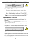
b. Loosen the lamp retaining thumb-screw and rotate the lamp until the O
3
REF reading on
display is 4500 mV
± 320 mV. Re-tighten the thumb-screw. (Note that the full range of
lamp adjustment can be achieved within ¼ revolution of the lamp. Note also that the O
3
REF display is updated approximately once every six seconds, and slow rotation of the
lamp is needed for proper adjustment.)
8-7


