Teledyne API Model 401 O
3
Photometric Calibrator Instruction Manual, 01124, Rev. J2
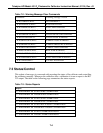
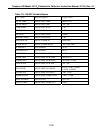
Table 7-8: Test Measurement Request Commands
Command Test Measurement
"?<CRLF>" RS-232 HELP screen
"T LIST<CRLF>" Summary of all Tests
"T O3MEAS<CRLF>" Current O
3
meas counts
"T O3REF<CRLF>" Current O
3
reference counts
"T SPRESS<CRLF>" Sample pressure
"T SFLOW<CRLF>" Sample flow rate
"T STEMP<CRLF>" Sample temperature
"T ALTEMP<CRLF>" Analyzer lamp temperature
"T BOXTEMP<CRLF>" Internal box temperature
"T DCPS<CRLF>" DC power supply output
"T CLKTIME<CRLF>" Current time-of-day
7.6 Viewing And Modifying Variables
The most powerful feature of the RS-232 interface is the ability of a host computer to view and
modify the calibrator's internal variables. Just as the operator modifies the variables by means of
the setup mode, the host computer modifies them by means of the RS-232 interface.
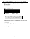
To view a variable's value, the host computer issues a command of the following format:
"V VARIABLE<CRLF>"
The CPU will respond by sending a message of the following format to the RS-232 output:
"V VARIABLE=VALUE WARNLO WARNHI <DATALO-DATAHI> <CRLF>"
In both cases "VARIABLE" is the name of the variable that is being viewed. "VALUE" is the
current value of the variable. "WARNLO" and "WARNHI" are the low and high warning limits,
respectively, but may not appear for all variables since some variables do not have warning
limits. "DATALO" and "DATAHI" are the low and high data entry limits, respectively, and are
given for all variables. The CPU will not set a variable's value or warning limits to values which
are outside of the data entry limits.
7-8


