Teledyne API Model 401 O
3
Photometric Calibrator Instruction Manual, 01124, Rev. J2
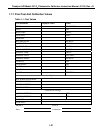
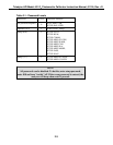
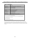
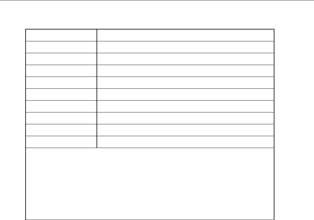
Table 2-2: System Modes
Mode Meaning
STBY xxxx (1) Standby mode (Photometer is operating normally)
ZERO CAL x (2) Zero check in progress
O
3
GN CAL x (2) Span check in progress
ASEQ xxx (5) x (2) Multi-point calibration in progress
HOLD OFF Hold off delay after power reset
D/A OUTPUT (3) Test analog output channels
BCAL ZERO Bench zero calibration
BCAL SPAN Bench span calibration
SETUP xxx (4) Configuring analyzer (operation continues)
(1) xxxx = AZS ( Auto Zero & Span programmed), AZ2S (Auto Zero & 2 span points; 25% &
100% of O
3
set concentration) programmed AZ5S
(Zero & 5 span points; 20%, 40%, 60%, 80% & 100% of O
3
set concentration) programmed.
(2) x = M (manual), A (auto), R (remote)
(3) diagnostic test modes
(4) xxx = software revision
(5) 0%, 20%, 25%, 40%, 60%, 80%, 100%
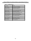
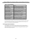
The message field shows test measurements or warning messages. Table 2-3 and Table 2-4
summarize the test measurements and warning messages and their meanings. Refer to Sections 4
and 5 for detailed information on viewing test measurements and warning messages and clearing
warnings.
2-5


