Teledyne API Model 401 O
3
Photometric Calibrator Instruction Manual, 01124, Rev. J2
NOTE
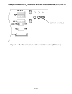
See Figure 1-4 for rear panel pneumatic connections. Span gas
should only come into contact with PTFE or glass. Leak check
all fittings with soap solution.
Maximum pressure for leak check is 15 PSIG.
6. Connect the pump exhaust to a suitable vent outside the analyzer area.
CAUTION
Connect the exhaust fitting on the rear panel (see Figure 1-5) to a
suitable vent outside the analyzer area.
7. For internal pressurized zero air using an external dry air supply connect AIR IN port to a
clean, dry air supply (see Figure 1-6).
NOTE
For best O
3
generator stability and to avoid moisture condensation,
it is recommended that zero air be dried to approximately -20°C dew
point.
For external pressurized dry zero air using an external dry pressurized source (see Figure 1-
6) proceed as follows:
a. Remove cap plug from the tee of zero air scrubber assembly and connect external dry
zero air line instead (air pressure should be about 30-40 psi).
b. Install the cap plug to dry air inlet port.
c. Verify the power is off and unplug O
3
GENERATOR pump's power cable connector.
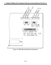
8. Connect a recording device to the terminal strip connections on the rear panel (see
Figure 1-2). See Table 9-4 for setting proper analog output voltage jumpers.
9. Connect the power cord to an appropriate power outlet (see the serial number tag for correct
voltage and frequency).
NOTE
Power plug must have ground lug.
1-8


