Teledyne API Model 401 O
3
Photometric Calibrator Instruction Manual, 01124, Rev. J2
8.5 DC Power Supply
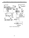
Overall performance of the DC power supply may be checked by observing the value displayed
during test DCPS. If this value, a composite of the five (5) regulator outputs, deviates by more
than 10% from the value recorded in Table 1-1 of this manual under Test Values, the outputs of
the individual regulators should be measured.
Test points 1, 2, 3 and 4 provide connection to the temperature outputs on drawing no. 00016 in
Appendix D.
8.6 CPU
If the display is operating and the green sample light is on, the CPU should be operating. If not,
check the red LED on the CPU board itself, it should be blinking.
If the RED led on the CPU board is not blinking, make the following checks:
1. Verify the +5 Volt supply on the power connector to the CPU Backplane.
2. Check for any loose memory chips on the CPU board.
3. Try removing and reseating the CPU – V/F Card assembly in the motherboard.
8-6


