


16
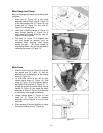
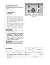
Fence Adjustment
1. To laterally adjust the aluminum fence
plates, loosen the two fence locking levers
(refer to C, Figure 8), slide the fence plates
to the required positions and tighten locking
levers.
The aluminum fence plates
should be adjusted inward so that the
opening at the spindle is just enough to clear
the cutter.
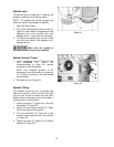
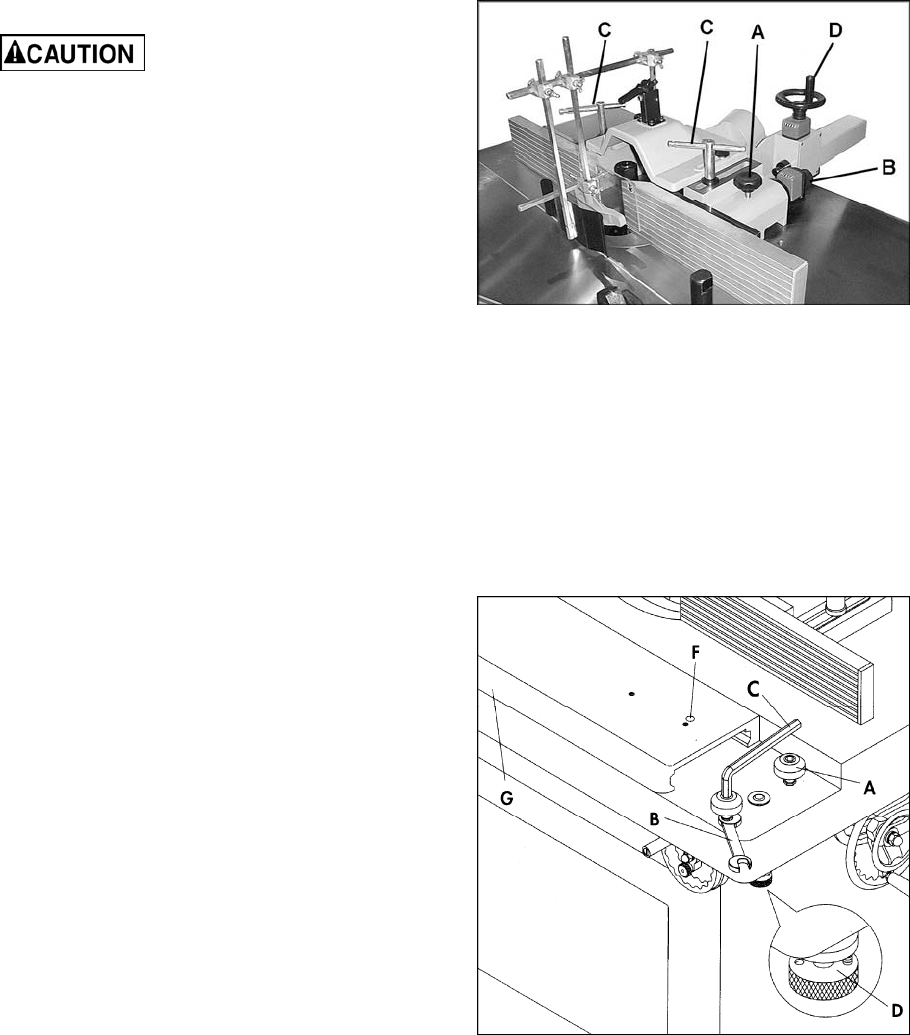
2. The right fence plate (infeed) can be moved
independently, in or out, depending on the
type of shaping operation that is being
performed. To move the right fence plate in
or out, loosen the locking knob (A, Figure
23) and turn the adjusting knob (B, Figure
23). Precise movements are possible by
using the dial indicator beneath the knob.
When finished, re-tighten locking knob (A,
Figure 23).
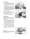
3. The entire fence assembly can be rapidly
positioned on the table by slightly loosening
both locking handles (C, Figure 23) and
moving the fence assembly to desired
position by rotating the handwheel (D,
Figure 23). Use the dial indicator for more
precise measurement. Re-tighten the
handles (C, Figure 23) when finished.
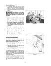
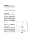
Sliding Table Adjustment
There are six adjustable eccentric rollers (A,
Figure 24) on the sliding table. Wherever the
sliding table is unstable or not traveling in line,
adjust the sliding table as follows:
1. Loosen the roller (A, Figure 24) with a hex
wrench (C, FIgure 24).
2. Use open end wrench (B, Figure 24) to
rotate the rollers as needed.
3. Lock the setting of the roller by using the
hex wrench (C, Figure 24).
To operate the sliding table (F, Figure 24) pull
down on the knurled knob (D, Figure 24) and
rotate it 180 degrees until the opposite hole
engages the pin. The sliding table can then be
moved back and forth.
To lock the sliding table in centered position,
move the sliding table flush with the main table.
Pull down on the knurled knob (D, Figure 24)
and rotate it 180 degrees until it engages the
pin.
Figure 23
Figure 24