


12
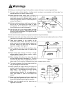
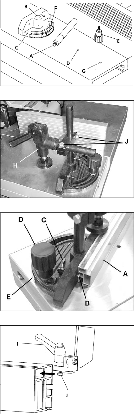
Miter Gauge and Clamp
Mount miter gauge and clamp to the sliding table
as follows:
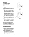
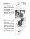
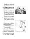
1. Insert post (A, Figure 10) of the clamp
assembly down through hole (B, Figure 10)
of the miter gauge body (C, Figure 10), and
thread post (A, Figure 10) into hole (D,
Figure 10) of sliding table.
2. Insert shaft of locking handle (E, Figure 10)
down through opening (F, Figure 10) of
miter gauge and thread shaft into hole (G,
Figure 10) of sliding table.
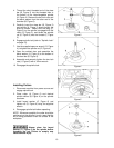
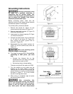
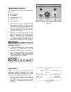
3. The clamp (H, Figure 11) is supplied with
the miter gauge to securely hold the
workpiece when shaping small pieces
across the grain. The clamp should be
mounted as shown, and can be adjusted by
loosening the screws (J, Figure 11).
Miter Fence
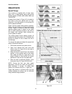
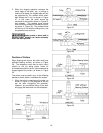
1. Slide the miter fence (A, Figure 12) onto the
two square nuts (B, Figure 12) that are
attached to the threaded part of the locking
levers (C, Figure 12).
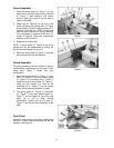
2. To slide miter fence to the left or right,
loosen locking levers (C, Figure 12), slide
fence (A, Figure 12) to the desired position
and tighten locking levers (C, Figure 12). To
change the angle of the fence loosen locking
handle (D, Figure 12) and rotate the entire
assembly. A scale (E, Figure 12) is provided
to indicate the miter angle of the fence.
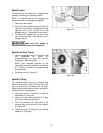
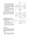
3. Loosen locking screw (I, Figure 13) and
insert nut (J, Figure 13) of workstop
assembly into the channel on end of fence
as shown.
4. Slide workstop to desired position on fence
and tighten locking screw (I, Figure 13).
Figure 10
Figure 11
Figure 12
Figure 13