


12 - 37 12 - 37
MELSOFT
12. USEFUL FUNCTIONS
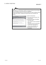
DISPLAY/SETTING DATA
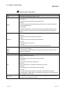
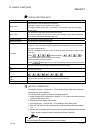
Item Description
Trace Set the trace intervals within the range 1 to 256.
Trigger
Choose the actual trace starting condition.
• Unconditional
Trace starts at the start request of the peripheral device.
• Busy ON
Trace starts actually when the started signal (X1/X2/X3) turns on after the start request
from the peripheral device.
• PC trigger ON
Trace starts actually when 1 is written to the buffer memory address 5050 of the AD75
under the control of the sequence program after the start request from the peripheral
device.
Trace stop
Choose the trace stopping condition.
• Buffer full
Trace stops when the trace data area becomes full.
• Endless
Trace stops at the stop request of the peripheral device.
• Error stop
Trace stops when an error occurs.
• Trace point
Trace stops when the number of trace points reaches the specified value.
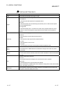
Data 1
Data 2
Represents the trace data No.
When AD75P#-S3 or AJ65BT-D75P2-S3 is selected in Change AD75 model, only data 1
may be traced.
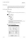
Axis No.
Choose the axis combination whose data will be traced.
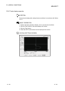
In the track data of the trace results, the first axis number indicates the X axis and the second
the Y axis.
Data
Choose the data type to be traced.
• Pos. inst
Feed address-based track data given from the AD75 to the servo amplifier.
• Real value
Track data based on the actual address of the AD75M.
When AD75P#-S3 or AJ65BT-D75P2-S3 is selected in Change AD75 model, the traceable
data is the speed command only.
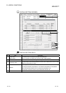
"OK" button
Click this button to close the Trace condition dialog box and display the axis numbers and
data types on the tracks display main screen.