


8 MHD56037 - Edition 5
Traceability
Load bearing parts are documented to provide traceability. The
documentation includes chemical and physical properties of raw
material, heat treating, hardening, tensile and charpy tests as
required for the part.
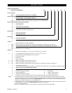
Units with M1, M2 or M3 in the model code have traceable load
bearing components.
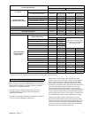
M1–Material Traceability certificates according to EN 10204 (Ex
DIN 50049) 2.2 on load bearing parts. Conformity documents
affirm (by manufacturer) that parts are in compliance with
requirements of order based on non-specific inspection and
testing (i.e. results are typical material properties for these parts).
M2–Material Traceability certificates according to EN 10204 (Ex
DIN 50049) 3.1b on load bearing parts. Conformity documents
affirm (by a department independent of the manufacturing
department) that the actual parts are in compliance with the
requirements of the order based on specific inspection and testing
(i.e. results are actual material properties for these parts).
M3–Material Traceability certificates according to EN 10204 (Ex
DIN 50049) 3.1b on load bearing parts. Conformity documents
affirm (by a department independent of the manufacturing
department) that the actual parts used in the product are in
compliance with the order based on specific inspection and
testing (i.e. results are actual material properties for these parts in
a finished, as delivered condition).
Components with part numbers ending in CH or CHA are charpy
parts for use under extreme cold conditions. Traceability
requirements must be stated when reordering these parts for
continued certification.
INSTALLATION
Prior to installing winch, carefully inspect it for possible shipping
damage.
Winches are supplied fully lubricated from the factory. Before
operation check oil levels and adjust as necessary. Use the proper
type of oil as recommended in “LUBRICATION” section.
CAUTION
• Owners and users are advised to examine specific, local or
other regulations, including American Society of Mechanical
Engineers Standards and/or OSHA Regulations which may
apply to a particular type of use of this product before
installing or putting winch to use.
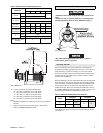
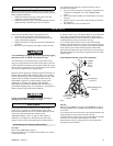
Mounting
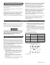
Refer to Dwg. MHP0133 and Table 1 on page 8, and Table 2 on
page 9.
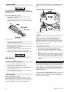
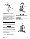
Care must be taken when moving, positioning or mounting the
winch. In most cases, lifting lugs have been provided to assist in
handling the winch. If lug locations are improper for your specific
installation, great care should be taken to ensure that winch, when
lifted, will be properly balanced. Determine weight of your winch
by referring to “SPECIFICATIONS” section. Lift winch 3 to 4
inches (75 to 100 mm) off ground.
Verify winch is balanced and secure before continuing lift.
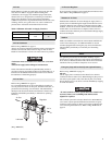
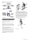
Mount winch so axis of drum is horizontal and that motor vent cap
is not more than 15° off top vertical center. If winch is to be
mounted in an inverted position, motor case must be rotated to
position vent cap at top.
1. The winch mounting surface must be flat and of sufficient
strength to handle rated load plus weight of winch and
attached equipment. An inadequate foundation may cause
distortion or twisting of winch uprights and side rails
resulting in winch damage.
2. Make sure mounting surface is flat to within 0.005 inch
(0.127 mm) per inch of drum length. Shim if necessary.
Refer to Table 1.
3. Mounting bolts must be 3/4 inch (18 mm) Grade 8 or better.
Use self-locking nuts or nuts with lockwashers.
4. Tighten 3/4 inch (18 mm) mounting bolts evenly and torque
to 380 ft lbs (515 Nm) for dry thread fasteners. If fasteners
are plated, lubricated or a thread locking compound is used,
torque to 280 ft lbs (380 Nm).
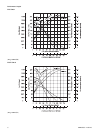
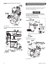
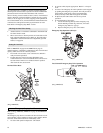
5. Maintain a fleet angle between sheave and winch of no more
than 1-1/2°. The lead sheave must be on a center line with
drum and, for every inch (25 mm) of drum length, be at least
1.6 feet (0.5 metre) from the drum. Refer to Dwg. MHP2123
on page 9.
6. Do not weld any part of winch.
Table 1–Mounting Surface Tolerance
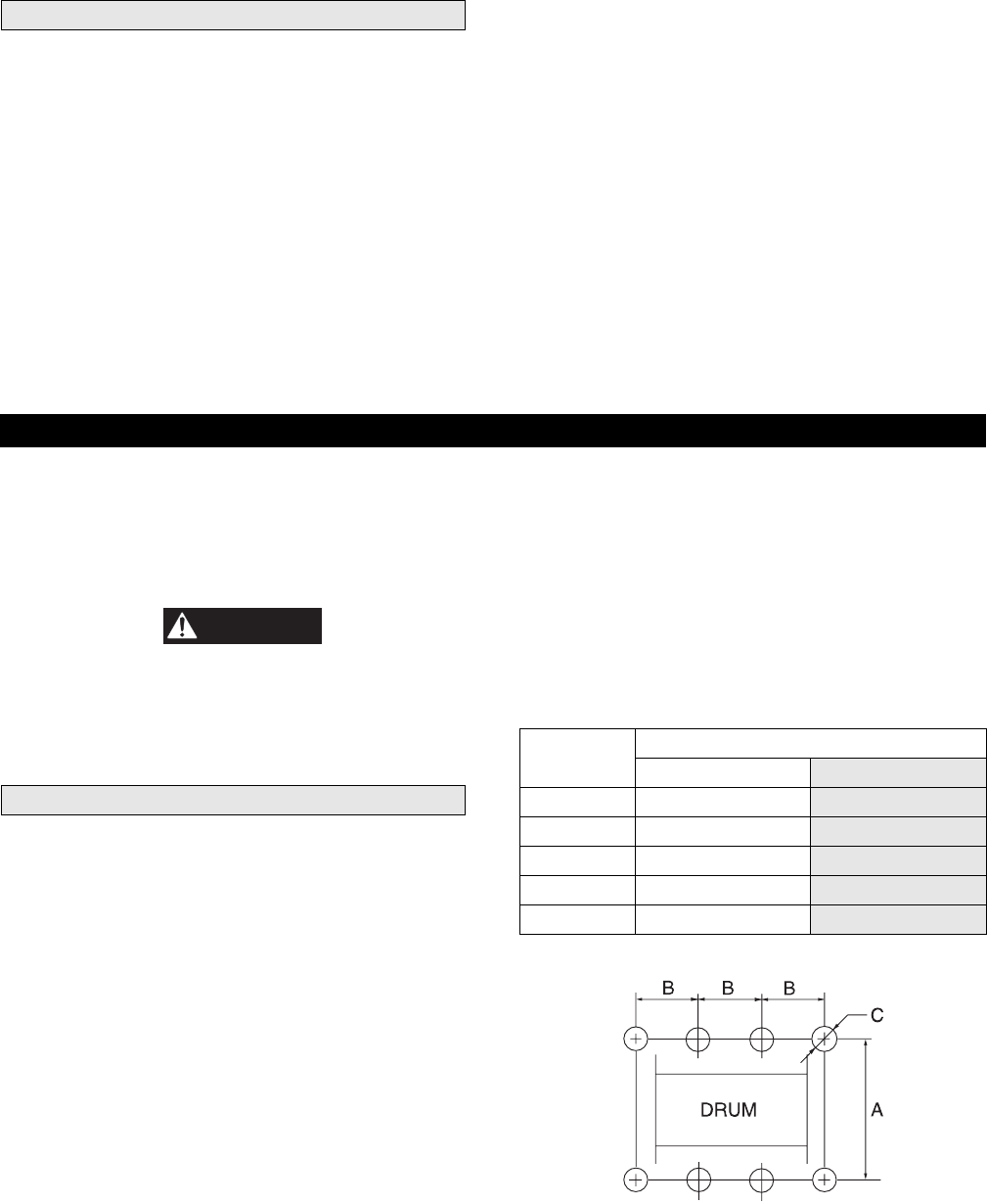
Winch Bolt Hole Mounting Dimension Drawing
(Dwg. MHP0133)
Drum
Length
Mounting Surface Minimum Flatness
inch mm
12 0.06 1.52
16 0.08 2.03
24 0.12 3.05
30 0.15 3.81
36 0.18 4.57