


34 MHD56037 - Edition 5
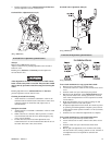
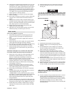
3. Install two seal rings (251) on each end of rotary valve
(250). Place bearing (252) onto the rear of rotary valve (250)
and press into position. Press only on bearing inner race.
With rotary valve housing (247) exhaust flange down, install
rotary valve into housing.
4. Install ‘O’ ring (244) into motor housing (217).
5. Install rotary valve housing gasket (243) onto rotary valve
housing. With exhaust flange down on bench, install motor
housing (217) onto rotary valve housing. Check for any
evidence of damage to ‘O’ ring when rotary valve housing is
fully engaged. Install and tighten capscrews (1) to 50 ft lbs
(68 Nm).
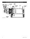
6. If removed, press crank bearing (228) on crank assembly
(231). Apply pressure only on inner race of bearing.
7. Place crank assembly on a work bench with oil slinger (230)
down and slide the sleeve (232) (with tang up) on crankpin.
8. Slide connecting rod bushing (233) over sleeve (232) and
first connecting rod ring (234) with chamfer up.
9. Install connecting rods (206) in same order as removed, with
all feet pointing in same direction, using first connecting rod
ring (234) to hold one side of connecting rod feet.
10. Slide second connecting rod ring over other side of
connecting rod feet with chamfer on ring facing down
(toward stem of connecting rod).
11. Slide crank shaft valve end over crank pin while
simultaneously aligning tang on sleeve (232) with slot in
crank shaft.
12. Rotate and position crank shaft valve end relative to crank
pin to allow installation of lock pin (235).
13. Tap lock pin (235) in place and install pin nut (237). Torque
nut to 60 ft lbs (81 Nm).
14. Install cotter pin (236) and bend ends over.
15. Install roll pin (240) and bearing (228) into valve end of
crank shaft.
16. Check that all connecting rods move freely around crank.
Position crank assembly into motor housing (217). Ensure
bearing (228) is seated and connecting rods (206) are
centered in cylinder holes.
NOTICE
• Make certain roll pin (240) and three lugs on rotary valve
(250) line up with corresponding hole and lugs on crank shaft.
• Do not allow rotary valve to slide back in rotary valve
housing (247). If rotary valve slides in too far, seal ring (251)
will lock-up in internal grooves of rotary valve housing (247)
and restrict further assembly.
17. Rotate crank assembly until one connecting rod (206) is at
the top of its stroke. Install a piston (204) with its rings (202)
and (207) to connecting rod with wrist pin (203) and
retaining rings (205).
18. Install a new cylinder head gasket (209) before installing
cylinder liner (208).
19. Install cylinder liner over the piston by compressing both
piston rings and with a single band ring compressor.
20. Install cylinder head (201) over cylinder and secure cylinder
head to motor housing with four capscrews (200). Torque
capscrews to 60 ft lbs (81 Nm).
21. Repeat Steps 17 through 20 with remaining cylinders.
22. Rotate motor by hand. Motor should rotate without binding.
23. Install mounting flange (216) and gasket (226) on front of
motor housing. Make sure notches on both parts are aligned.
24. Lightly lubricate ‘O’ ring (5) and install in groove on motor
adapter (6).
NOTICE
• ‘O’ ring, item 5 listed in step 24 refers to part number 51459
as shown on winch assembly Dwg. MHP0157
on page 40. This
part must be placed between mounting flange (216) and motor
adapter (6).
25. Temporarily install capscrews and nuts finger tight to retain
motor adapter (6).
26. Install eye bolts (213) and vent cap assembly (210) in motor
housing.
27. Ensure oil drain and level plugs (225) are installed.
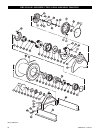
Reduction Gear Assembly
Refer to Dwg. MHP0157 on page 40.
NOTICE
• It is important to maintain a clean work area when reduction
assemblies are reassembled. During reassembly clean each
part thoroughly and lightly coat with appropriate lubricant as
described in ‘Recommended Lubricants’
on page 19 of the
“LUBRICATION” section.
1. Install bearing (49) and retainer ring (50) in gear carrier (47).
2. Lubricate and install ‘O’ rings (51) on ring gear (53).
3. Align capscrew holes and dowel pins with gear carrier (47)
and install ring gear (53). Ensure ‘O’ rings are not damaged
during installation.
4. Install planet assembly (54).
5. Install thrust bearing (55) into sun gear (56). Install retainer
ring (57) on sun gear and locate in planet assembly (54).
6. Align capscrew and dowel holes and install input housing
(59). Apply a light coating of Loctite
® 262 to capscrew (60)
threads and install by hand. Equally tighten capscrews in a
diametrically opposed pattern to allow for equal compression
of housing onto ring gear (53) and gear carrier (47). When
ring gear and input housing flanges are flush with gear
carrier torque capscrews to 95 ft lbs (128 Nm).
7. Install dowel pins (52) and tap into position until slightly
below input housing flange.
8. Install planet assembly (58) onto sun gear (56).
9. Lubricate and install ‘O’ rings (62) on ring gear (63).
10. Install dowel pins (70) in ring gear (63) so they extend an
equal distance on both sides of ring gear.
11. Align capscrew holes and dowel pins and install ring gear
(63) on input housing (59). Using a soft hammer or mallet,
carefully tap dowel pins and ring gear (63) onto input
housing until mating flanges are flush. Ensure ‘O’ rings are
not damaged during installation.
12. Place thrust bearing (55) in sun gear (66) and install sun gear
into planet assembly (58).
13. Install planet assembly (67) onto sun gear (66).
14. Align capscrew holes and dowel pins and install spacer (71)
onto ring gear (63). Using a soft hammer or mallet, carefully
tap spacer onto ring gear until mating flanges are flush.
Ensure ‘O’ rings are not damaged during installation.
15. Lubricate and install ‘O’ rings (62) on ring gear (72).
16. Using a soft hammer or mallet, carefully tap ring gear (72)
onto spacer (71). Ensure ‘O’ rings are not damaged during
installation.
17. Install sun gear (69) in planet assembly (67).