18 MHD56037 - Edition 5
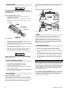
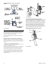
pull rod and ensure locking pin engages and is seated in drum
hole and gland deep groove.
WARNING
• Ensure that all braking mechanisms are engaged and all
personnel are clear of winch load and rigging before
disengaging locking pin.
• Extremely difficult locking pin release is an indication that
load is held by locking pin and braking mechanisms are not
functioning properly. Do not release locking pin until load
control is established.
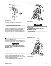
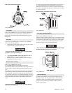
To Disengage:
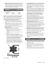
1. Pull out, straight away from outboard upright, pull rod (140)
and rotate clockwise 90°. Align pin (135) with the shallow
groove in gland (138) and release pull rod. Ensure locking
pin (136) is clear of the drum (80) flange and pin is seated in
gland shallow groove.
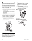
Limit Switch (optional feature)
Pre-set limit switch settings prevent winch wire rope payout and
haul-in by stopping air flow to the winch motor when a defined
set point has been reached. It is the owner’s and operator’s
responsibility to adjust winch operating limits prior to using
winch.
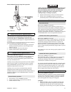
To adjust set points refer to ‘Adjustments’ in “MAINTENANCE”
section.
WARNING
• Ensure limit switch set points are established and operating
properly before using winch.


