


MHD56037 - Edition 5 27
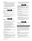
3. Rotating adjustment screw counterclockwise will decrease
pressure required to activate overload valve.
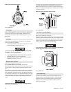
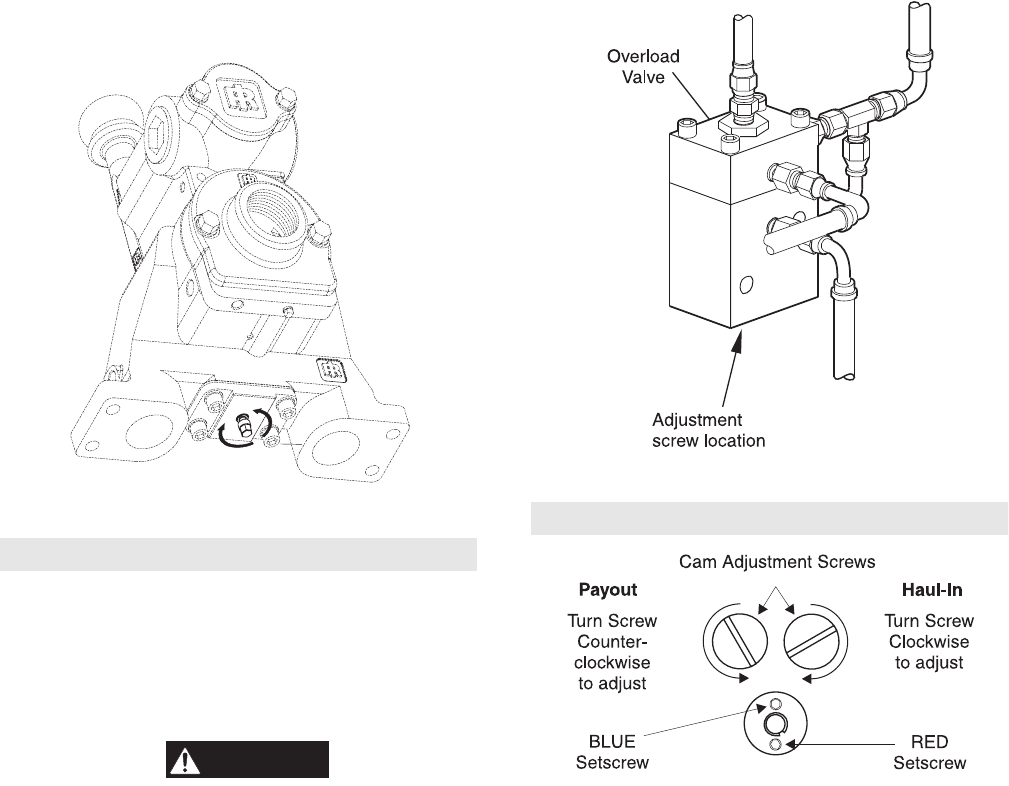
Overload Valve Adjustment (new style)
(Dwg. MHP2216)
Overload Valve Adjustment (optional feature)
old style
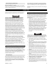
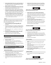
Refer to Dwg. MHP1678 on page 27.
Adjust overload valve by turning adjustment screw located at
bottom of valve.
Rotating screw clockwise will increase pressure required to
activate shutoff valve.
WARNING
• This adjustment can cause overload device to NOT activate
before winch’s safety limit is exceeded. This procedure should
only be done by personnel trained in testing and servicing this
winch.
Rotating adjustment screw counterclockwise will decrease
pressure required to activate shut off valve.
Checking Overload Valve Setting:
1. Attach load line to a load that is calibrated to 150% of the
maximum load for which winch is rated. Move control lever
to haul-in position. If winch lifts load, adjust screw as
described below.
Setting the Overload:
1. Attach load line to a load that is calibrated to 150% of winch
rated capacity.
2. When control lever is moved to haul-in position, overload
valve should activate shut off valve. Reset emergency stop
valve, valve is adjusted.
3. If winch lifts load, lower load. Turn adjustment screw
counterclockwise in ¼ turn increments until shut off valve is
activated. After each ¼ turn, retest winch.
Overload Valve Adjustment (old style)
(Dwg. MHP1678)
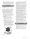
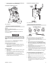
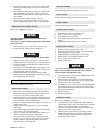
Limit Switch Adjustment (optional feature)
(Dwg. MHP0607)
To set winch maximum wire rope payout limit switch:
1. Remove access plate from top of limit switch.
2. Loosen blue setscrew in center of limit switch, below access
cover.
3. Position winch wire rope at desired payout position.
4. Rotate left cam adjustment screw counterclockwise until it
fully activates cutoff valve, causing system air to vent. 2¾
turns of the cam adjustment screw are required for each full
cam revolution.
5. Hold cam adjustment screw in position (venting air) and
tighten blue setscrew to lock cam in place.
6. If required, adjust haul-in limit switch. Test winch set points
by operating winch through three complete cycles to ensure
consistent limit switch operation within +/- 2 feet (2/3 metre)
of set points.
7. Install access cover when final adjustments are complete.
To set winch maximum wire rope haul-in limit switch:
1. Remove access plate from top of limit switch.
2. Loosen red setscrew in center of limit switch, below access
cover.
3. Position winch wire rope at desired switch activation
position.
4. Rotate right cam adjustment screw clockwise until it fully
activates cutoff valve, causing system air to vent. 2¾ turns of
cam adjustment screw are required for each full cam
revolution.