


30 MHD56037 - Edition 5
NOTICE
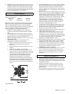
• Do not disassemble planetary gear assemblies (54), (58) and
(67).
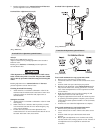
K5B Motor Disassembly
Refer to Dwg. MHP2093 on page 44.
1. Remove five capscrews (1) from exhaust flange (253) or
(254). Do not remove the two capscrews (255) from throttle
valve assembly (260).
2. Remove rotary valve housing (247) by pulling it out of
motor housing (217) as an assembly with exhaust flange
(253) or (254).
CAUTION
• Do not remove the exhaust flange (254) until rotary valve
(250) has been removed from rotary valve housing (247).
3. Remove rotary valve (250) by pulling it out from assembly
through the motor housing end of rotary valve housing (247).
4. Remove exhaust flange (254) and throttle valve assembly
(260) by removing capscrews (255) and (257), respectively.
5. Remove each cylinder head (201) by removing four
capscrews (200). Remove head gasket (209).
6. Pull cylinder liner (208) straight out.
7. Position piston (204) at top of its stroke. In this position,
with cylinder liner pulled out in step 7, wrist pin (203) can
be removed. Remove one retainer ring (205) from either side
of piston (204). Push wrist pin (203) out by hand from one
side. If wrist pin is too tight it is acceptable to carefully heat
piston to 200° F (93° C) or less and then push wrist pin out.
NOTICE
• If piston, wrist pin, connecting rod or cylinder liner are to be
re-assembled, number each set. Also add radial alignment
marks for each piston and cylinder liner to motor housing.
8. Remove remaining cylinder liners and pistons as described in
steps 7 and 8. To remove crank assembly, all pistons and
cylinder liners must be removed.
9. Crank assembly (231) can now be removed with oil slinger
(230) by pulling straight out from motor housing (217). Use
care while guiding connecting rods (206) through inside of
motor housing.
Crankshaft Disassembly
1. Remove cotter pin (236) and pin nut (237).
2. Remove lock pin (235) by carefully driving it out of its
location. Use care not to damage pin threads.
3. Pull crankshaft valve end (231) off crankshaft.
4. Remove connecting rod rings (234), connecting rod bushing
(233), sleeve (232) and connecting rods (206). Record five
connecting rod (206) numbers and foot directions so they
can be re-installed in same order.
5. Oil slinger (230) does not have to be removed unless
damaged. If removal is required, heating of five screws (229)
may be necessary to loosen Loctite
® connection.
Control Valve Removal and Replacement
Refer to Dwg. MHP2036 on page 50 or MHP0165 on page 54.
Replacement of K5B control valve with K5C2 control valve.
1. Turn off air supply to valve and disconnect main air supply
line at motor.
2. Disconnect auxiliary air line(s) from fitting(s) located on
control valve.
3. Remove muffler and/or exhaust piping.
4. Remove capscrews (1) and (255), and washers (96) from
exhaust flange cap (254). Discard gasket (317).
5. Remove capscrews (257) and washers (96) from control
valve.
6. Remove control valve from rotary housing and discard
gasket (248).
7. Install gaskets (946) and control valve assembly (900)
securing with capscrews (951) and washers (949).
8. Install gasket (970) and exhaust cap (971) to rotary housing
on motor.
9. Install fittings (957), (958) and muffler (959) on control
valve. These are optional parts.
K5C2 Control Valve Disassembly
Refer to Dwg. MHP2036 on page 50.
Handle Removal
It is not recommended to disassemble handle.
1. Carefully pry off plug (935).
2. Remove capscrew (901) and tablock washer (909).
NOTICE
• Observe spring (937) connection during disassembly. This
spring is under tension and is required to return handle to
neutral position.
3. Carefully pull handle assembly (930) from reverse valve
(943). Remove spring (937).
Reverse Valve Removal
1. Remove capscrews (938), (925) and washers (924) from seal
bracket (939). Remove seal bracket from housing. Remove
and discard ‘O’ rings (941) and (942).
2. Remove capscrews (901) and washers (902) from exhaust
flange (955). Remove flange from housing. Remove and
discard ‘O’ ring (942).
3. Move reverse valve (943) out exhaust flange side of housing
until ball (916) is visible on reverse valve. Allow ball (916)
to drop out of bushing (944) and remove ball (916).
4. Remove bushing (944) out exhaust flange side of housing.
NOTICE
• Dowel pin (945) allows the bushing to be removed only from
the exhaust flange side of housing. Ball (916) retains reverse
valve (943) in bushing (944).
• Do not remove reverse valve (943), bushing (944) and ball
(916) at the same time, damage may occur to bushing.
• Take care to not allow ball (916) to drop in motor. If this
occurs it may be necessary to disassemble motor to retrieve
ball (916).