MHD56037 - Edition 5 5
SPECIFICATIONS
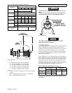
Model Code Explanation
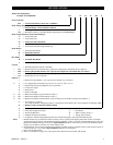
Example: FA5-24MK320P FA5 - 24 M K 320 P
Series (Capacity)
FA5 = Air Powered Winch (5 metric ton / 11,000 lbs.)
Drum Flange Height or Man Rider®:
- = Standard flange: 27 inch (660 mm) diameter
T = Tall flange: 35 inch (890 mm) diameter
MR =
Man Rider
TM
(Refer to FA5 Man Rider
TM
Supplement Form #MHD56042)
Drum Length (Distance between drum flanges):
12 = 12 inch (306 mm)
16 = 16 inch (406 mm)
24 = 24 inch (610 mm) (Standard)
30 = 30 inch (760 mm)
36 = 36 inch (915 mm) Tall Flange Winch only
Drum Brake:
A = Automatic Drum Brake
M = Manual Drum Brake
X = None
Disc Brake:
K = Automatic Disc Brake
X = None
Control:
1 = Winch mounted lever throttle. (Standard)
* 2XX = Remote full flow lever throttle (XX = Specify hose length (feet). Maximum 20 ft. (6 metres))
* 3XX = Remote pilot pendant throttle (XX = Specify hose length (feet). Maximum 50 ft. (15 metres))
* 4XX = Remote pilot lever throttle (XX = Specify length (feet). Maximum 50 ft. (15 metres))
* 5XX = Remote electric over air throttle†
Options: **
7 = Drum Grooving (Number = wire rope size in sixteenths, e.g. 7/16 inch) †
** C = Low Temperature Components; specify -10° C (14° F) or -20° C (-4° F)
D = Drum Divider Flange and additional wire rope anchor †
E = Construction Cage†
G = Drum Guard
L = Drum Locking Pin
** M1 = Material Traceability (typical material results) ††
** M2 = Material Traceability (actual material results) ††
** M3 = Material Traceability (actual material results for these parts in finished, as-delivered condition) ††
N =
Type Approval – Specify:
A = American Bureau of Shipping (ABS); N = Det Norske Veritas (DNV); R = Lloyd’s Register of Shipping (LRS)
P = Marine Grade Corrosion Preventative Finish
Q = Special paint U = Underwound wire rope operation †
S = Limit Switch (upper and lower) V = Press Roller
T = Tensioning Manifold W = Witness; please specify **
Z = Sandblast and Carbozinc Primer X = Testing; please specify
-E = Compliance with European Machinery Directive (includes Emergency Stop and Overload Protection)
Notes: * Remote throttles are provided with 10 feet (3 metres) of hose. Specify hose lengths greater than 10 feet. For lengths
greater than 20 ft. (6 metres) with the Remote Full Flow Throttle, or 50 ft. (15 metres) with the Remote Pilot Lever and
Remote Pilot Pendant Throttles contact your Ingersoll
Rand distributor or the factory for control acceptability. Metric
lengths are provided for reference only, order lengths in feet.
** Documentation, witness testing and material traceability available; must be requested at time of order. Specify options or
contact the factory or your nearest Ingersoll Rand distributor for information.
† Not covered in this manual.
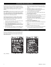
†† Refer to ‘Traceability’on page 8 for a description of the differences between M1, M2 and M3.


