32 MHD56037 - Edition 5
5. Inspect drum band brake lining for oil, grease and glazing. If
drum band brake lining is oil-soaked replace brake bands as
a set. Remove glazed areas of band brake lining by sanding
lightly with a fine grit emery cloth.
6. Measure thickness of drum band brake lining. If drum brake
band linings are less than 0.062 inch (2 mm) thick anywhere
along edges replace brake bands (128) as a set.
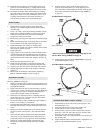
7. Inspect cylinder bores. Minor scratches in bore lining may
be repaired by lightly honing to remove. Refer to tolerances
listed below for acceptable clearances. Replace liner if deep
scratches or gouges are apparent. Measure inside diameter of
liner. If measurement is greater than 4.764 inches (121 mm)
replace liner. ‘Ring Gap’ may also be used to determine
wear; place compression ring into liner, using a piston, push
ring until approximately half way in liner and measure ‘Gap’
— 0.003 inch (0.076 mm) is normal; replace rings, or liner,
if ‘Gap’ exceeds 0.020 inch (0.51 mm).
Repair
Actual repairs are limited to removal of small burrs and other
minor surface imperfections from gears and shafts. Use a fine
stone or emery cloth for this work.
1. Worn or damaged parts must be replaced. Refer to the
applicable parts listing for specific replacement parts
information.
2. Inspect all remaining parts for evidence of damage. Replace
or repair any part which is in questionable condition. Cost of
the part is often minor in comparison with cost of redoing
job.
3. Smooth out all nicks, burrs, or galled spots on shafts, bores,
pins, or bushings.
4. Examine all gear teeth carefully, and remove nicks or burrs.
5. Polish edges of all shaft shoulders to remove small nicks
which may have been caused during handling.
6. Remove all nicks and burrs caused by lockwashers.
Assembly
General instructions
• Use all new gaskets and seals.
• Replace worn parts.
• Assemble parts using match marks attached during
disassembly. Compare replacement parts with originals to
identify installation alignments.
• Lubricate all internal parts with rust and oxidation inhibiting
lubricant, ISO VG 100 (SAE 30W).
K5C2 Control Valve Assembly
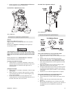
Refer to Dwg. MHP2036 on page 50.
Reverse Valve Assembly
1. Insert reverse valve (943) into bushing (944) with ball slot
oriented UP, approximately 2-1/2 in. (64 mm).
2. Insert bushing (944) and reverse valve (943) into valve
housing (917) from exhaust flange side, ensuring that groove
in bushing is aligned with pin (945).
3. Insert ball (916) onto reverse valve platform. With finger,
push ball (916) in housing until ball hits end of reverse
valve.
4. Holding ball (916) in position on reverse valve platform,
rotate reverse valve from neutral position to approximately
45 degrees in either direction. Ball will ‘walk’ up side of
reverse valve platform and move in ball hole in bushing.
NOTICE
• Do not rotate reverse valve past a 90 degree position, it may
result in the ball (916) falling in motor.
5. Slowly push reverse valve, while still in the 45 degree
position, the rest of the way in housing until flush with
surface. From other side of valve rotate reverse valve back to
neutral position, ball should be seated in ball slot at that time.
6. Lubricate ‘O’ ring (942) and place it in groove in exhaust
flange (955).
7. Secure exhaust flange (955) to valve housing with capscrews
(901) and washers (902).
8. Insert ‘O’ ring (941) into seal bracket (939). Lubricate ‘O’
ring (942) and place into groove in seal bracket.
9. Place seal bracket over end of reverse valve. Using finger
pressure, press until seal is seated on reverse valve and seal
bracket is seated on valve housing. Secure with washers
(924) and capscrews (925) and (938).
Pilot Valve Assembly
NOTICE
• For easier installation it is recommended to use IR pilot valve
tool (920). This must be purchased separately.
1. Install pilot valve assembly (910).
2. Apply thread sealant Loctite 567® to pilot valve assembly
(910), place pilot valve assembly into valve housing. Use a
large flat tipped screw driver to engage slots in pilot seat and
tighten until pilot assembly is 1/8 in. (3.175 mm) from
housing bore.
3. Insert plug (912) and tighten.
Piston Assembly
1. Lubricate and install ‘O’ rings (921) and (923) on piston
(922).
2. Insert assembled piston into valve housing (917) from
handle side.
3. Secure with gasket (918), piston cover (919), washers (902)
and capscrews (901).
4. Place poppet seal (907) into poppet cap (906). Place this
assembly into valve housing and seat on piston (922).
5. Place spring (905) over this assembly.
6. Secure with gasket (904), poppet cover (903), washers (902)
and capscrews (901).
Handle Assembly
1. Place spring (937) over reverse valve handle end in seal
bracket.
NOTICE
• Spring (937) will have to be ‘Cocked’ over stud in seal
bracket. This will ensure handle returns to neutral.


