MHD56037 - Edition 5 13
Initial Operating Checks
Winches are tested for proper operation prior to leaving factory.
Before winch is placed into service the following initial operating
checks should be performed.
1. When first running motor inject some light oil into inlet
connection to provide initial lubrication.
2. When first operating winch it is recommended that motor be
operated slowly in both directions for a few minutes.
For winches that have been in storage the following start-up
procedures are required.
1. Give the winch an inspection conforming to requirements of
“Winches Not in Regular Use” in the “INSPECTION”
section.
2. Pour a small amount of ISO VG 32 (SAE 10W) oil in motor
inlet port.
3. Operate motor for 10 seconds in both directions to flush out
any impurities.
4. The winch is now ready for normal use.
OPERATION
The four most important aspects of winch operation are:
1. Follow all safety instructions when operating winch.
2. Allow only people trained in safety and operation of this
winch to operate this equipment.
3. Subject each winch to a regular inspection and maintenance
procedure.
4. Be aware of winch capacity and weight of load at all times.
CAUTION
• To avoid damage to rigging, the structure supporting rigging
and winch, do not “two-block” the end of wire rope.
* Two blocking occurs when winch wire rope is multi-reeved
using two separate sheave blocks which are allowed to come into
contact with each other during winch operation. When this occurs
extreme forces are exerted on wire rope and sheave blocks which
may result in equipment and or rigging failure.
Operators must be physically competent. Operators must have no
health condition which might affect their ability to act, and they
must have good hearing, vision and depth perception. The winch
operator must be carefully instructed in his duties and must
understand the operation of winch, including a study of the
manufacturers’ literature. The operator must thoroughly
understand proper methods of hitching loads and must have a
good attitude regarding safety. It is the operator’s responsibility to
refuse to operate winch under unsafe conditions.
WARNING
• Winch is not designed or suitable for lifting, lowering or
moving persons. Never lift loads over people.
Winch Controls
The spring loaded, motor mounted, live air manual throttle
control valve is supplied as a standard feature on this winch.
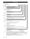
Optional remote throttle controls are available. Reference model
code on the winch nameplate and compare it to the
“SPECIFICATIONS” section,
on page 5 of this manual, to
determine your configuration. The throttle controls provide
operator control of motor speed and direction of drum rotation.
Winch Mounted Air Throttle (standard feature)
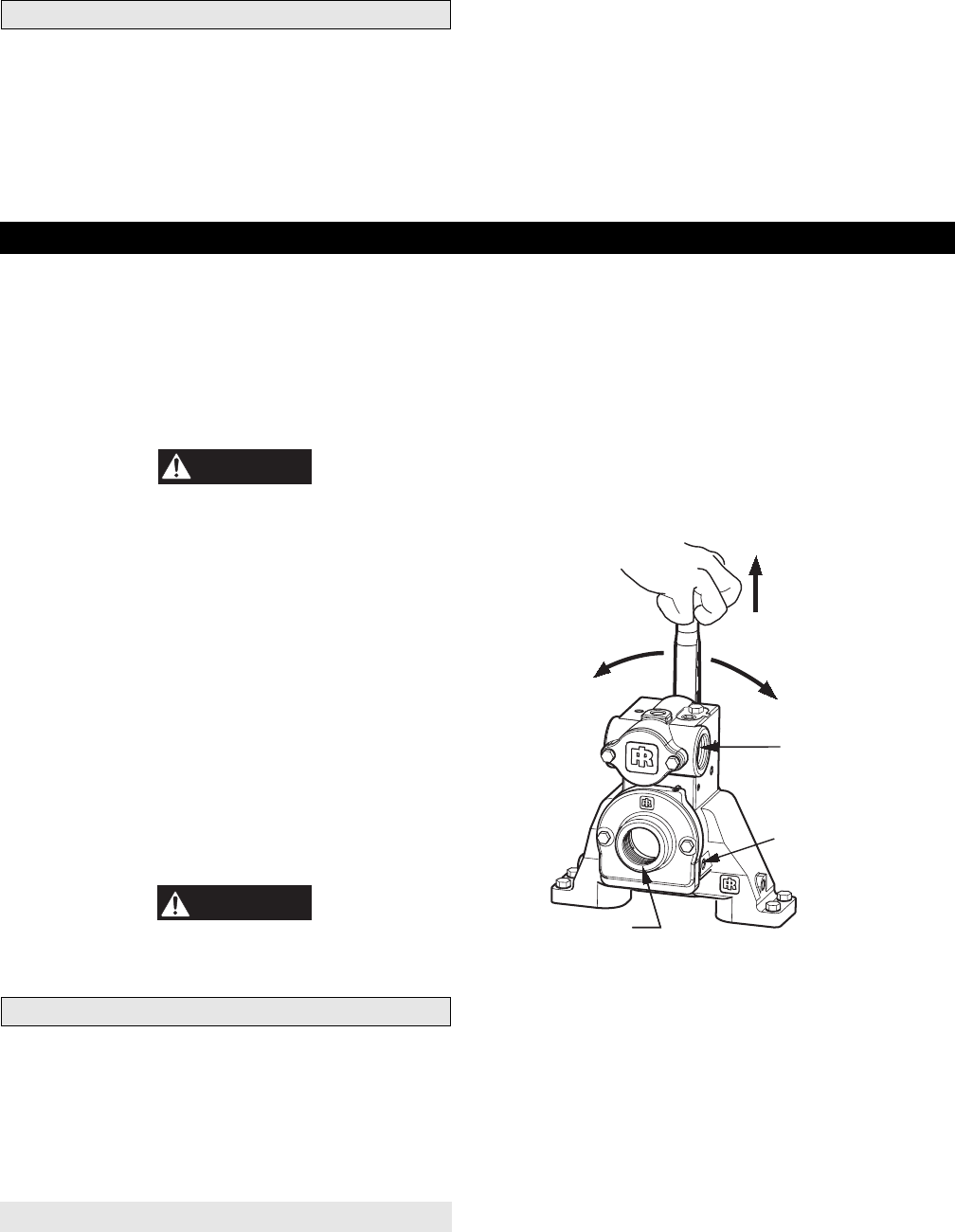
New Style
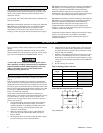
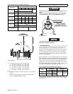
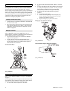
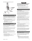
Refer to Dwg. MHP1809 on page 13.
The spring loaded, live air, manual control throttle valve mounts
to the rotary housing.
To operate control valve, place palm of hand on control knob and
wrap fingers around flange of sliding handle. Squeeze fingers,
lifting sliding handle up to unlock control lever. Shift control lever
in desired direction to payout or haul-in wire rope.
As viewed from the air motor end, move the control throttle
handle to the right (clockwise) to payout wire rope and to the left
(counterclockwise) to haul-in wire rope. Avoid sudden movements
of the control valve to ensure smooth operation of the winch.
When released, handle will return to the neutral or center position.
The sliding handle will drop down to engage and lock the control
handle in place.
Winch Mounted Throttle Control Valve Operation
(Dwg. MHP1809)
old style
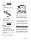
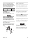
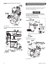
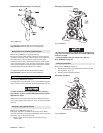
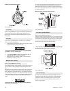
Refer to Dwgs. MHP0165 on page 54 and MHP0566 on page 14.
The spring loaded, live air, manual control throttle valve mounts
to air motor.
As viewed from air motor end, move control throttle handle to the
right (clockwise) to payout wire rope and to the left
(counterclockwise) to haul-in wire rope. Avoid sudden movements
of control valve to ensure smooth operation of winch.
When winch is not in use, engage latch to prevent inadvertent
movement of control throttle.
Lift Slider
Handle
UP to
Unlock
Exhaust Port
1-1/2 NPT
Air Inlet Port
1-1/4 NPT
Brake Release Port
1/4 NPT
Payout
Haul-In


