


ASSEMBLY
INSTRUCTIONS
FITNESS SYSTEMS
R
HOIST
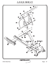
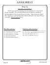
42 - Cam Belt
44 - Cam Belt
45 - Serrated Clamps
46 - Belt Retainer Shaft
47 - Tube
(110” LG.)
(42” LG.)
(1 5/8” x 2 1/16” LG.)
Part Descriptions
P - 3/8”-16 x 3/4” Button Head Screw
Q - 1/4”-20 x 1 1/4” Socket Head Screw
R - 1/4”-20 x 3/4” Button Head Screw
AG - 3/8” Lock Washer
AH - 3/8 Flat Washer
AP - 1/4” Lock Washer
BC - 3/8” Lock Nut
BD - 1/4” Lock Nut
CL - 3 1/4” Pulley
(White Zinc)
(Black Zinc)
(Black Zinc)
(White Zinc)
(White Zinc)
(Black Zinc)
(Black Zinc)
(White Zinc)
Hardware Descriptions
2403 Assembly
Page 17
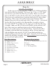
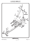
FRAME ASSEMBLY
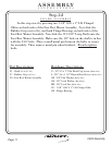
Step 2g
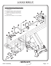
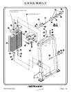
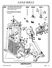
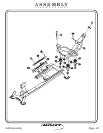
In this step start by attaching the Belt Assembly to the Weight
Assembly (prior to attaching the Cam Belt). Place smooth side of Cam
Belt on the Pulley and Cam. Next slide the Cam Belt through the Pulley
Bracket on the top of the Weight Cage. Then use a Seat Clamp On tool to
secure the two 3 1/4” Pulleys to the Weight Cage under the Cam Belt.
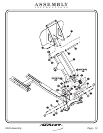
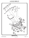
Slide the Cam Belt into the top slot of the 1 5/8”x 2 1/16” LG. Tube (Fig.
1). Loop the end of the Cam Belt and feed it back up through the slot,
keeping the loop open (Fig. 2). Next slide the Belt Retainer Shaft through
the Cam Belt and line up the holes, then secure to the 1 5/8” x 2 1/16”
LG. Tube (Fig. 3). Next attach the Cam Belt by bringing it down and
through the pulley bracket behind the 3 1/4” Pulley. Now bring the Cam
Belt around the Large Cam Assembly and in between the Serrated
Clamps. Then wrap the Cam Belt down and around the Serrated Clamp
and above another Serrated Clamp and secure all of the Serrated Clamps
together. Next wrap the short cam belt on the Small Cam Assembly as
shown. bolts.Wrench tighten