


ASSEMBLY
INSTRUCTIONS
FITNESS SYSTEMS
R
HOIST
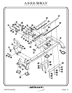
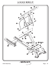
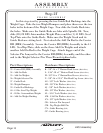
21 - Shaft
22 - Rubber Grip
23 - Aluminum Ring
24 - Foot Rest Assembly
25 - Foot Rest Leg Assembly
26 - Shaft
56 - Shaft
(12 31/32” LG.)
(12 9/32 LG.)
(8 29/32” LG.)
(4 7/16” LG.)
27 - Rubber Grip (36” LG.)
Part Descriptions
G - 1/2”-13 x 1” Flat Head Cap Screw
CB - Insert
CC - Bumper Stopper
CF - 1” I.D. Flanged Oilite
(White Zinc)
Hardware Descriptions
2403 Assembly
Page 9
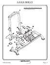
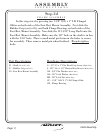
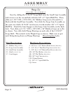
FRAME ASSEMBLY
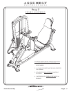
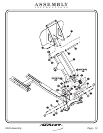
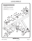
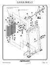
Step 2c
In this step start by pressing four 1” O.D. x 3/4” I.D. Flanged Oilites
into the Foot Rest Leg Assembly. Next insert the 1” Dia. x 4 7/16” Shaft
into the lower part of the Foot Rest Leg Assembly. Make sure the 1/8”
hole on the Shaft is in line with the 3/16” hole on the Foot Rest Assembly.
Then insert any small metal pin to hold the shaft with 1/8” hole to align
for bolting. Then remove the small metal pin when finished. Place
Rubber Grip (cut to fit) on both ends of the 1”Dia x 4 7/16”. Next attach
the Foot Rest Leg Assembly to the Running Base Assembly as shown.
Insert the 8 29/32” Long Shaft onto the upper part of the Foot Rest Leg
Assembly. Make sure the 1/8” hole on the Shaft is in line with the 3/16”
hole. Then insert any small metal pin into the shaft for alignment.
Remove the small metal pin when finish bolting. Attach the Foot Rest
Assembly to the Foot Rest Leg Assembly as shown. For the final step,
slide the Rubber grip onto the 12 31/32” Long Shaft and slide two
Aluminum Rings onto both side of the shaft. Attach the 12 31/32” Long
Shaft to the Foot Rest Assembly. Then bolts including all
previously hand tightened bolts
Wrench tighten
.