


ASSEMBLY
INSTRUCTIONS
2403 Assembly
Page 13
FITNESS SYSTEMS
R
HOIST
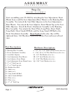
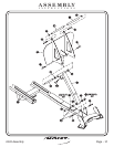
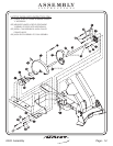
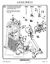
Start by sliding the 14 25/32” Long Shaft onto the Small Cam Assembly
and secure it on the second hole with the 3/8” x 2” Spiral Roll Pin. Then,
slide on 1.175” O.D. x .9375 I.D. x 36” Rubber Grip (cut to fit) until it is
flush with the Small Cam Assembly. Next slide the Large Cam Assembly on
the same size shaft (14 25/32”) and secure it with another 3/8” x 2” Spiral
Roll Pin. Attach the Cam Stopper to the Large Cam Assembly on the back
hole. Next slide on 1.175 ” O.D. x .9375 I.D. x 36” Rubber Grip (cut to fit)
as shown. Now slide both Flange Bearings on each side of the 14 25/32”
Long Shaft. Then attach to the Weight Cage as shown. Make sure to put
zerk fitting facing down on Flange Bearings boltsWrench tighten .
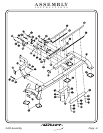
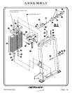
27 - Rubber Grip
29 - Large Cam Assembly
30 - Small Cam Assembly
31 - Shaft
57 - Cam Stopper
(36” LG.)
(14 25/32” LG.)
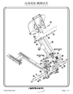
Part Descriptions
J - 3/8”-16 x 1 1/2” Button Head Screw
G - 1/2”-13 x 1” Flat Head Cap Screw
V - 3/8”-16 x 1 1/4” Button Head Screw
AH - 3/8” Flat Washer
AK - 3/8” Flat Washer
BB - 3/8” Lock Nut
CH - Flange Bearing
CJ - 3/8” x 2 “ Spiral Roll Pin
CQ - Insert
(White Zinc)
(White Zinc)
(Black Zinc)
( White Zinc)
(Black Zinc)
(Black Zinc)
Hardware Descriptions
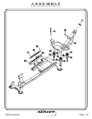
FRAME ASSEMBLY
Step 2e