


ASSEMBLY
INSTRUCTIONS
FITNESS SYSTEMS
R
HOIST
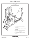
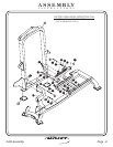
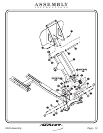
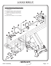
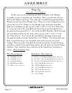
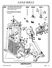
In this step start by pressing two 1 3/8” O.D. x 1” I.D. Flanged
Oilites on both sides of the Foot Rest Mount Assembly. Next s
. Then remove metal pin when finished.
bolts.
Wrench tighten
lide the
Rubber Grip (cut to fit), and both Flange Bearings on both sides of the
Foot Rest Mount Assembly. Now slide the 12 31/32” Long Shaft onto the
Foot Rest Mount Assembly. Make sure the 1/8” hole on the shaft is in line
with the 3/16” hole. Place a small metal pin between the holes to secure
for assembly
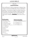
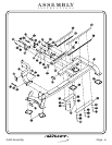
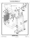
21 - Shaft
28 - Foot Rest Mount Assembly
(12 31/32” LG.)
27 - Rubber Grip (36” LG.)
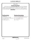
Part Descriptions
G - 1/2”-13 x 1” Flat Head Cap Screw
J - 3/8”-16 x 1 1/2” Button Head Screw
AH - 3/8” Flat Washer
AK - 3/8” Lock Washer
BB - 3/8” Lock Nut
CF - 1 3/8” O.D. X 1” I.D. Flange Oilite
CH - Flange Bearing
(White Zinc)
(White Zinc)
(White Zinc)
(Black Zinc)
(Black Zinc)
Hardware Descriptions
2403 Assembly
Page 11
FRAME ASSEMBLY
Step 2d