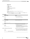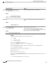
!Use LDP (configured i/f default)
interface POS3/0/1
ip address 192.168.0.44 255.0.0.0
mpls ip !Enable hop-by-hop MPLS forwarding
mpls label protocol tdp !Use TDP for this interface
The configuration of Router 2 also uses the mpls label protocol ldpcommand in interface configuration
mode. To specify LDP for all interfaces, use the mpls label protocol ldpcommand in global configuration
mode without any interface mpls label protocol commands.
Configuring the mpls ip command on an interface triggers the transmission of discovery Hello messages
for the interface.
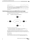
Establishing Nondirectly Connected MPLS LDP Sessions Example
The following examples illustrate the configuration of platforms for MPLS LDP nondirectly connected
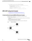
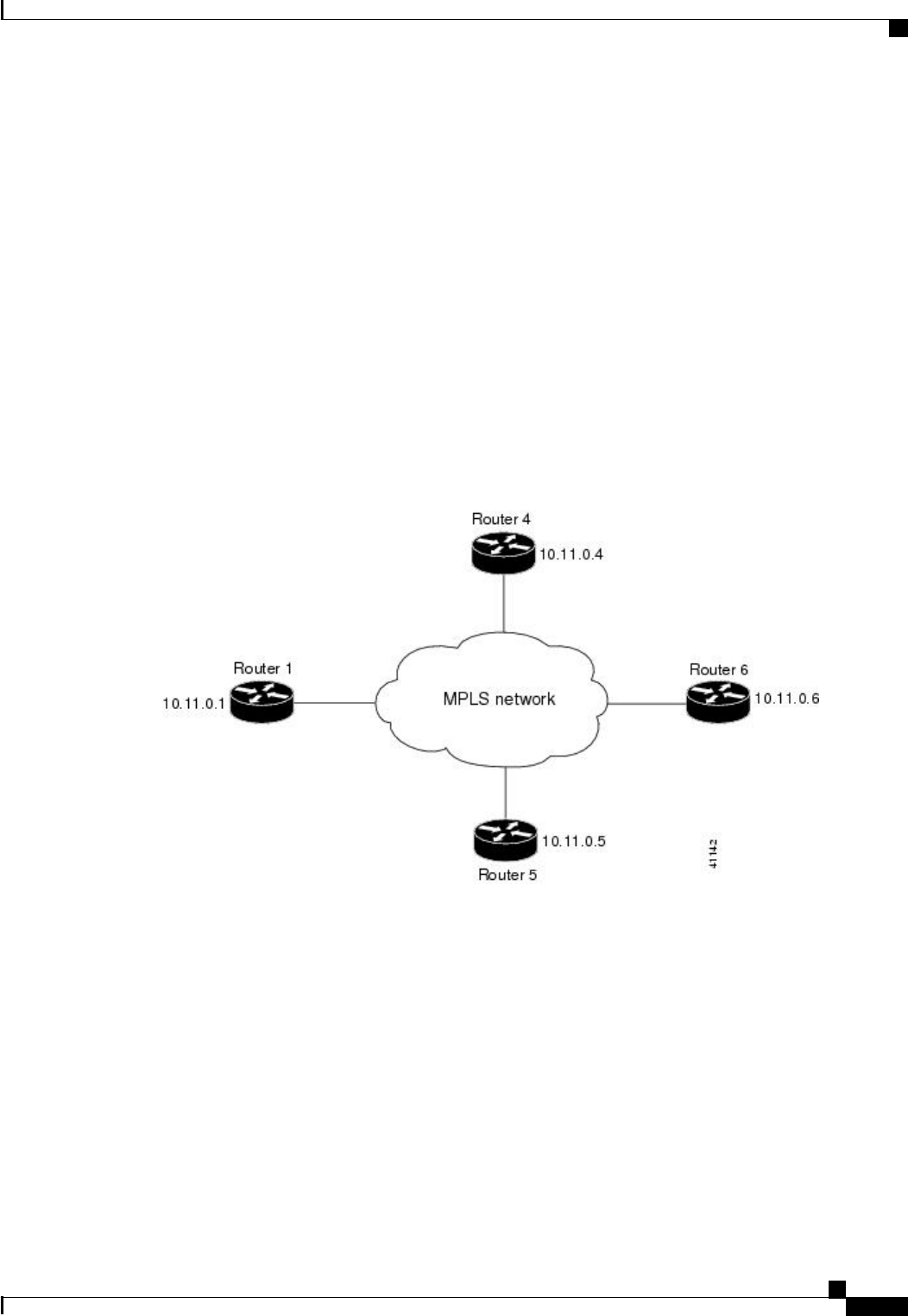
sessions using the sample network shown in the figure below. Note that Routers 1, 4, 5, and 6 in this
sample network are not directly connected to each other.
Figure 2 Sample Network for Configuring LDP for Targeted Sessions
The configuration example shows the following:
• Targeted sessions between Routers 1 and 4 use LDP. Routers 1 and 4 are both active.
• Targeted sessions between Routers 1 and 6 use LDP. Router 1 is active and Router 6 is passive.
• Targeted sessions between Routers 1 and 5 use TDP. Router 5 is active.
These examples assume that the active ends of the nondirectly connected sessions are associated with
tunnel interfaces, such as MPLS traffic engineering tunnels. They show only the commands related to
configuring LDP targeted sessions. The examples do not show configuration of the applications that initiate
the targeted sessions.
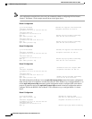
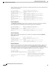
Router 1 Configuration
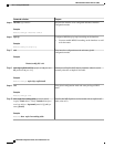
Tunnel interfaces Tunnel14 and Tunnel16 specify LDP for targeted sessions associated with these
interfaces. The targeted session for Router 5 requires TDP. The mpls label protocol ldp command in
Establishing Nondirectly Connected MPLS LDP Sessions Example
MPLS LDP Configuration Examples
MPLS LDP Configuration Guide, Cisco IOS Release 12.4
23


