Pelco Manual C539M-A (12/01) 9
2.1.4 CONFIGURATION SWITCH
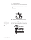
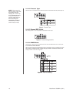
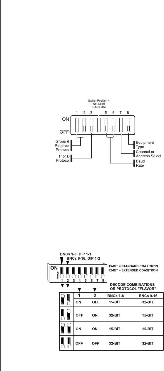
The decode of configuration switch functions is indicated in Figure 5 and discussed in detail
in the paragraphs that follow.
This configuration switch configures the translator with respect to the following functions:
1. BNC Input Group (allocated in x8 groupings) and protocol “flavor” (15 or 32 bit Coax-
itron)
2. Choice of P or D protocol.
3. Communications channel baud rate (under P protocol only).
4. Cascade addressing (16/32 channel or translator address range)
5. Type of 32-bit protocol (Intercept or Spectra).
Figure 5. Configuration Switch
NOTE:
Configuration switch positions are read only at power-up time; therefore,
switch changes made after power is applied have no effect until power is recycled.
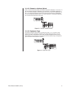
2.1.4.1 BNC Input Grouping (Receiver Side)
The sixteen BNCs to which Coaxitron receivers are attached are split into x8 groups (1-8
and 9-16). Each group is further defined as entertaining one of two protocol “flavors”: 15- or
32-bit (these are references to 15-bit standard Coaxitron or 32-bit extended Coaxitron, re-
spectively). Therefore, a combination of 15- and 32-bit protocol “flavors” on the same unit is
possible. Conversely, if both x8 groups on the same translator are assigned the same proto-
col flavor, then the entire translator interfaces only 15-bit or only 32-bit Coaxitron receivers.
Figure 6. BNC Input Group and Protocol “Flavor”
IMPORTANT:
If any x8
group combination is set to
32-bit, DIP switch 1-8 must
be set to restrict equipment
use for the entire translator
to ONLY one equipment
type (receiver): Intercept or
Spectra.


