8 Pelco Manual C539M-A (12/01)
The breakdown, with respect to cascading for each controller, is as follows:
• For the 9760, cascading is allowed; addressing is no problem.
• For the MPT9500, addressing 32 receivers is no problem; it is not, however very prac-
tical as the controller itself is Coaxitron capable. See the remarks made in the
MPT
Controller Hookup
portion of section
3.2 Installation Configurations
.
• For the DX7000, only 16 receivers at a time are addressable, therefore it can handle
only one attached CXTA unit. This constraint is also necessary because the DX7000
can interface only 16 loop back video inputs.
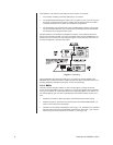
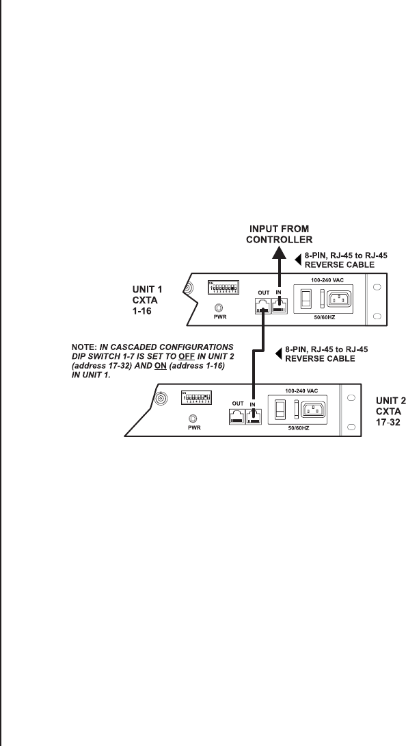
The data cable that runs between the labeled IN connector on the CXTA and the RJ-45
Sercom port connection located on the rear of the 9760 matrix controller (CM9760-CC1) is
provided. This is a reverse, 8-pin, flat cable (see Figure 4). Since this is the most often en-
countered configuration, the cable is provided.
Figure 4. Cascading
The provided data cable cannot be used (as is, out of the box) with the DX7000 or the
MPT9500. Each of these has different cabling requirements that are illustrated in the corre-
sponding installation examples (see Figures 15 and 16, respectively).
2.1.3 BNCs
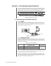
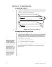
There are 16 pairs (32 total) of BNCs on each unit (see Figure 2). These are IN-OUT,
to-from, dual-function BNCs. The top or bottom row can be used as INPUTS or OUTPUTS.
If the top row of BNCs are used as OUTPUTs, the corresponding BNCs on the bottom row
are used as INPUTs, and vice versa. Characteristics and functions of BNC use are as fol-
lows:
• The BNCs are used for video input/output, command/control and in/out looping.
• Receiver access (by controllers) must correspond to the numbered BNC INPUT con-
nector to which the receiver is attached.
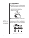
• The BNCs are numbered and addressed, left to right, 1-16. The BNCs on a cascaded
translator (the second unit) are addressed and numbered, left to right, 17-32. The ad-
dress reponse for each controller is set via DIP 1-7 (see Figure 10).


