


22 Pelco Manual C539M-A (12/01)
SECTION V: APPENDIX
5.1 COMMUNICATION PARAMETERS
There is only one basic set of signal interface rules that you must consider when wiring two
9760 communication devices together. Those rules are given in step 3 below.
Frustration arises only if the information you are given does not enable you to identify those
elements of the connection you need to know or if the information you need is not readily at
hand. You should not be satisfied to just plug in a cable “type” because you are told to with-
out having the slightest idea what to do if it doesn’t work. It’s easy enough to check the pa-
rameters for yourself so that when you do plug that cable in, you expect it to work. In fact,
you should be surprised if it doesn’t work.
You will never get in trouble when wiring two 9760 communication devices together, if you
know and follow the information contained in the following steps. You may not always need
all the information listed in all the steps, but you must always have enough information at
your disposal to follow the connection rules stated in step 3.
1. You should know or be given the location of Pin 1 on each of the device input/output,
plugs/connectors that you intend to wire together.
2. You should always be given the signal function that can be accessed at the Pin 1 loca-
tion.
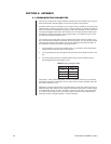
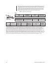
3. All communication devices in the 9760 System must be wired so that the result, if
checked against the following table, is true.
Table B. Signal Interface Table
Device A Device B
TX + RX +
TX – RX –
RX + TX +
RX – TX –
Given steps 1 and 2 and knowing step 3, you can successfully connect any two communi-
cation devices together to make them work. In many cases, a cable is provided. That’s OK.
Just check it before you use it.
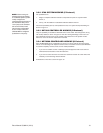
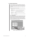
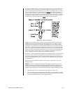
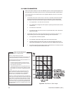
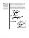
Depending on the physical geometry of the cable itself, you may also need to know how to
determine cable “type” before you can apply the rules above (see Figure 19). Most devices
in the 9760 family use RJ-45, 8-pin, flat cable to connect to each other. This is rigid cable
so, in effect, it has a cable “color” run across its width. This fact is used to determine the
cable type as either “straight” (parallel) or “reverse” (flipped).