


Pelco Manual C539M-A (12/01) 23
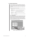
If a cable is “straight”, then pin 1 at one end of the cable goes to pin 1 at the opposite end
of the cable. If the connecting plugs on this cable interface two devices, then pin 1 on de-
vice one would physically be connected to pin 1 on device two. Straight cable is used in de-
vices where the signal pin run on the first device is
opposite that of the second device. If a
cable is “reverse”, then pin 1 on one end of the cable goes to pin 8 at the opposite end of
the cable. If the connecting plugs on this cable interfaced two devices, then pin 1 on device
one physically connects to pin 8 on device two. A reverse cable is used in devices where
the signal pin run on the first device is the same as that of the second device.
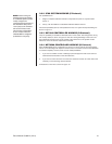
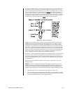
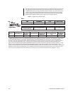
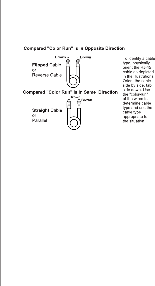
Figure 19. Cable Identification
The physical wiring differences for “straight” versus “flipped” came about because of the
relationship of the physical orientation of the attached plugs when the cable is created.
Almost all pieces of equipment connected to the CM9760-CC1 utilize “flipped” cables be-
cause there is a concerted effort to make the signal available at Pin 1 on all devices be TX+.
Thus, use of a “flipped” cable fulfills the requirement of step 3. TX+ (Controller) ends up at
RX+ (Pin 8) on the connected device, because the signal runs from Pin 1 to Pin 8 on each
device is the same. Some devices predate this effort or are simply wired in a different man-
ner. For these, either a straight cable or a non-standard wiring interface is used. How to
identify a “straight” cable from a “flipped” one is illustrated in Figure 19.
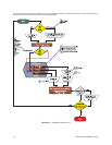
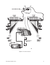
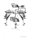
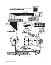
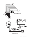
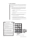
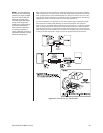
Sometimes, a physical disparity exists between two connecting devices such that the wiring
geometry you start with at one end is different from that at the other end. Nevertheless,
the wiring relationships stated in step 3 must be satisfied. Examples of this occurred in the
manual when connecting the CXTA to the DX7000 or to the MPT9500 (see Figures 15 and
16, respectively).
Both wiring scenarios utilized a wall block, which is part of a “wiring kit” that can be ob-
tained from Pelco.
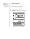
NOTE:
Do not be confused by the pasted-in wiring label located in the cap of the
wiring block that you sometimes see. Although signal functions are labeled for each
terminal pin, remember that this is a passive device and that the actual signal that
appears on any terminal pin is the one that you put there. Keep the following in mind:
1. Plan the wiring for each run ahead of time. Be surprised if it doesn’t work.
2. Verify any manual instructions that specify attachment of a certain cable “type”. Check
to be sure the right cable is packed and that the instructions given don’t run contrary to
the previously stated connection rules for signal interfaces.