


W6-LI System Board Manual
Chapter 2: Configuring the W6-LI
16
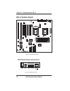
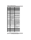
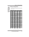
Connector Function Notes
J19-J20 ISA Bus Expansion Slots
J23 Power Supply Connector ATX Standard
J27 Front I/O Connector
" System Power On/Off 1 - Power; 2 - Ground
" Reset Switch 23 - Reset; 22 - Ground
" PC Speaker
Note: Jumper pins 26 and 27
to use the onboard speaker
27 - Speaker; 24 - +5V DC
" Power-On LED 20 - Positive; 18 - Ground
" IDE LED
Note: IDE and SCSI functions
share the same LED
13 or 16 - Positive; 15 - Negative
" Infrared 6 - +5V DC; 8 - Receive Data;
9 - Ground; 10 - Transmit Data
" Speaker (Buzzer)
Note: Jumper pins 26 and 27
to use the onboard speaker
Enabled (default)
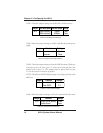
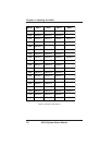
J28 Infrared Port Connector (Note:
Do not connect IR devices to
J27 & J28 simultaneously)
1 - Receive Data; 2 - Ground;
3 - Transmit Data; 4 - +5V Power
J29, J30 CPU Fan
(J29 - Primary)
(J30 - Secondary)
1 - 12+V Power; 2 - Ground;
3 - Status (Running or Stopped)
J31 Chassis Fan 1 - 12+V Power; 2 - Ground;
3 - Status (Running or Stopped)
J33 CD-ROM Audio Input 1 - Ground; 2 - CD-In Left Channel;
3 - Ground; 4 - CD-In Right Channel
J34 Modem/Telephony 1 - No Connect; 2 - MIC Out;
3 - Ground; 4 - Speaker Input
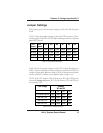
J35 Game Port/MIDI
MIC In
Line In
Line Out
Upper Level
Lower Level
Lower Level
Lower Level
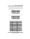
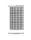
J36 Wavetable Upgrade 1 - Right Channel Input; 2 - Ground;
3 - Left Channel Input; 4 - Ground;
5 - No Connect; 6 - Ground;
7- Ground; 8 - Ground
J37 SCSI 50-pin Cable Connector Fast SCSI (optional)
J38 SCSI 68-pin Cable Connector Ultra Wide SCSI (optional)
U1 Primary P6 CPU Socket 8 (387-pin)
U2 Secondary P6 CPU Socket 8 (387-pin)
U25 System BIOS
Table 2-9B: Case & Peripheral Connections (cont.)