


MG-3D/M MULTIPURPOSE GRID AND ACCESSORIES
PN: 05.132.036.01 B2
Page 21 of 32
Meyer Sound Laboratories Inc.
www.meyersound.com
T: +1 510 486.1166
F: +1 510 486.8356
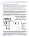
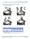
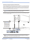
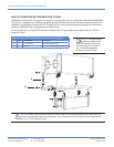
MG-3D/M GRID AND M3D/M3D-SUB FRONT FLOWN CONFIGURATION
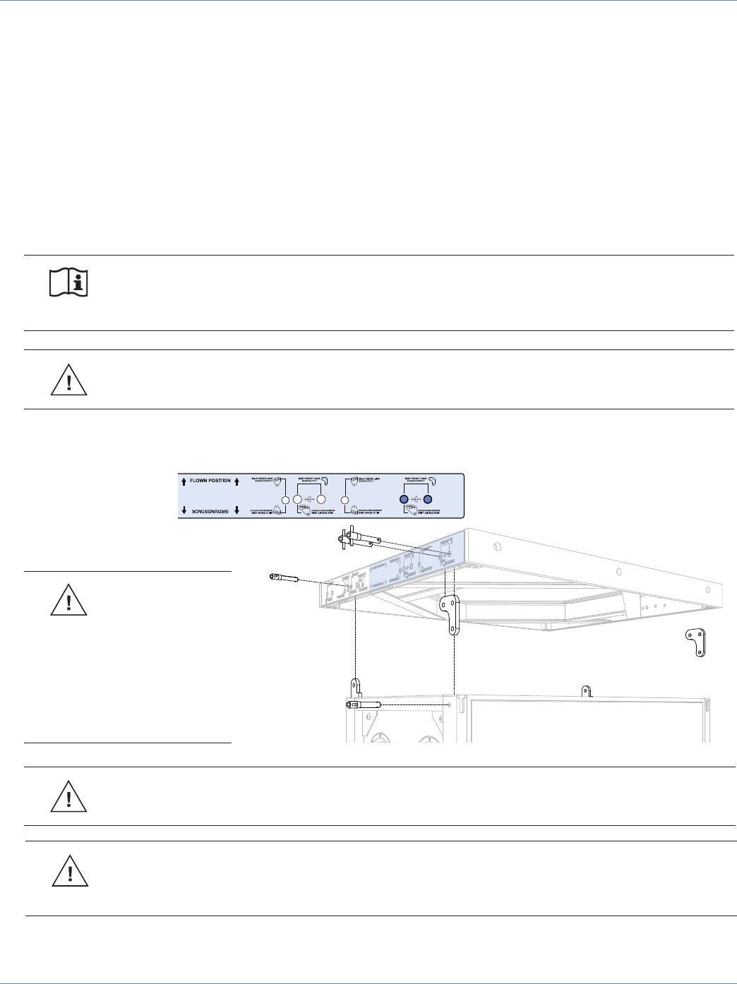
The MG-3D/M multipurpose grid allows you to fly M3D/M3D-Sub loudspeakers in two positions in relation to the
MG-3D/M grid. The “front flown” position is achieved by rigging M3D loudspeakers using the holes for the MTL-3D
transition links that are closer to the front of the MG-3D/M grid. This position is useful for achieving optimum down tilt
of the MG-3D/M grid and, subsequently, the array. Under the same circumstances (number of loudspeakers, angle
between loudspeakers, rating and position of motors) the front flown position will allow a larger down tilt than a rear
configuration.
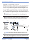
In flown configurations, the first M3D/M3D-Sub cabinet in the array is always connected to the MG-3D/M grid at 0°.
This is accomplished by using the captive rear link of the M3D/M3D-Sub in the rear and the MTL-3D link in the front.
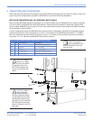
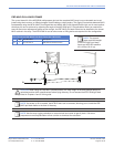
NOTE: To install a large array requiring severe vertical splay angles between cabinets, it’s useful to
temporarily introduce up tilt to the MG-3D/M grid as you connect individual cabinets to each other.
Depending on the application, a “rear flown” position may make more sense in this case.
CAUTION: A grid tilt greater than 45° is not allowed when flying M3D/M3D-Subs using the MG-3D/M
grid.
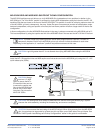
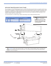
Install the MTL-3D transition links and M3D captive rear links as shown into the MG-3D/M grid, using the 1/2" x 2.5"
quick release pins (QRPs).
CAUTION: Always
use two 1/2" M3D
QRPs to secure the MTL-
3D transition links and one
to secure the captive rear
links to the MG-3D/M grid,
and be sure to lock them
into place. Do not use the
MILO 3/8" QRPs.
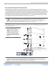
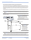
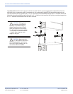
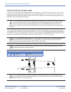
CAUTION: The leveling feet must always be detached from the MG-3D/M grid before flying a system.
Unscrew the entire assembly, including the threaded leg, and remove completely.
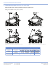
CAUTION: Never exceed the load rating of the MG-3D/M grid. When flying an array from the MG-3D/M
grid, it must always be supported by at least two pick-up holes, one of each side of the grid frame. See
the section “M3D System Load Ratings and Pickup Configurations” earlier in this guide for more details.