


MG-3D/M MULTIPURPOSE GRID AND ACCESSORIES
PN: 05.132.036.01 B2
Page 14 of 32
Meyer Sound Laboratories Inc.
www.meyersound.com
T: +1 510 486.1166
F: +1 510 486.8356
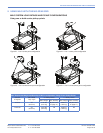
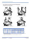
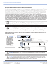
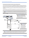
MG-3D/M GRID AND MILO FRONT FLOWN CONFIGURATION
The MG-3D/M multipurpose grid allows you to fly MILO loudspeakers in two positions in relation to the grid. The "front
flown" position is achieved by rigging MILO loudspeakers using the holes for the AlignaLinks that are closer to the
front of the grid. This position is most useful for achieving superior down tilt in the MG-3D/M grid and, subsequently,
the array. Under the same circumstances (number of loudspeakers, angle between loudspeakers, rating and position
of motors) the front flown position will allow more degrees of down tilt than a "rear flown" configuration.
In flown configurations, the first cabinet is connected to the MG-3D/M grid at 0°. This is accomplished by using the top
center hole in the MRAL-MILO rear AlignaLink (when used between cabinets, it is the 1° hole), which effectively provides
a 0° tilt angle. In addition to the splay angles of individual loudspeakers in an array, the up and down tilt of the MG-3D/M
grid and the array hung underneath can additionally be adjusted using chain motors, or differing lengths of steel cables or
chains. If a severe down tilt is needed, use the array rigging calculator to determine if the PBF-MILO pull back frame and
a separate motor are required. Visit www.meyersound.com/arraycalculator to find out how to download the calculator.
NOTE: To install a large array requiring severe vertical splay angles between cabinets, it’s useful to
temporarily introduce up tilt to the MG-3D/M grid as you connect individual cabinets to each other.
Depending on the application, a “rear flown” position may make more sense in this case.
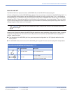
CAUTION: Out of the MRAL-MILO rear AlignaLink’s nine holes, you must use the top center hole
between the MG-3D/M grid and the first MILO loudspeaker in a flown configuration to ensure a 0° splay
angle between the MG-3D/M and the first MILO. Doing otherwise may force the hardware into an unnatural
position, which may produce an unpredictable tilt angle and/or cause damage to the link and MG-3D/M grid.
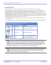
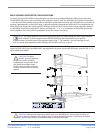
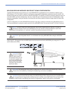
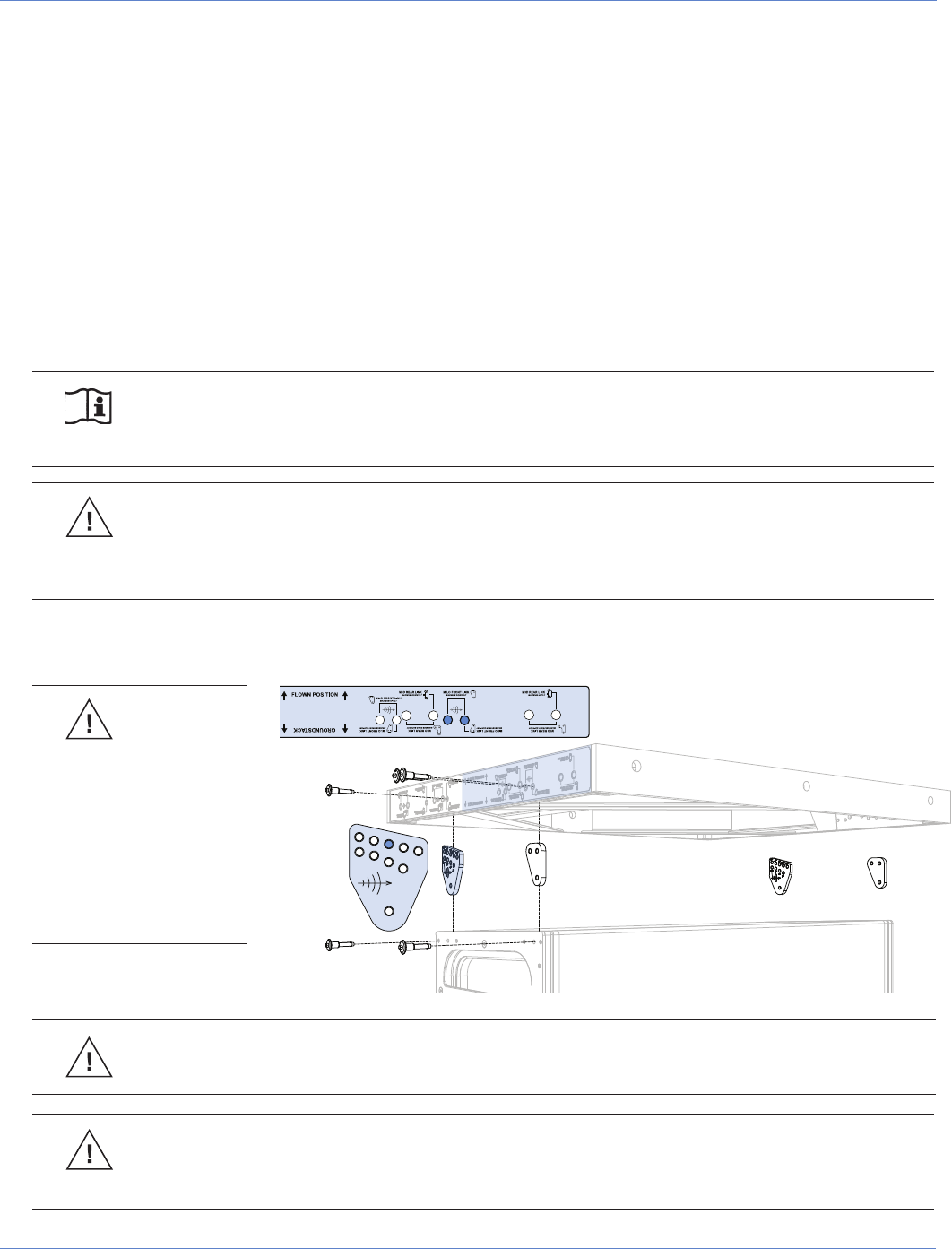
Install the MRAL-MILO rear and MFAL-MILO front AlignaLinks as shown into the MG-3D/M grid, using the 3/8" x 1.5"
quick release pins (QRPs).
CAUTION: Be sure to use the long 1.5" QRPs to secure the AlignaLinks to the MG-3D/M grid and that
the QRPs lock into place.
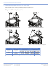
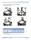
CAUTION: Never exceed the load rating of the MG-3D/M grid. When flying an array from the MG-3D/M,
it must always be supported by at least two pick-up holes, one of each side of the grid frame. See “MILO
System Load Ratings and Pickup Configurations” earlier in this chapter for more details.
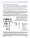
CAUTION:
The leveling
feet must always
be detached from
the MG-3D/M grid
before flying a
system. Unscrew
the entire assembly,
including the
threaded leg, and
remove completely.