MG-3D/M MULTIPURPOSE GRID AND ACCESSORIES
PN: 05.132.036.01 B2
Page 19 of 32
Meyer Sound Laboratories Inc.
www.meyersound.com
T: +1 510 486.1166
F: +1 510 486.8356
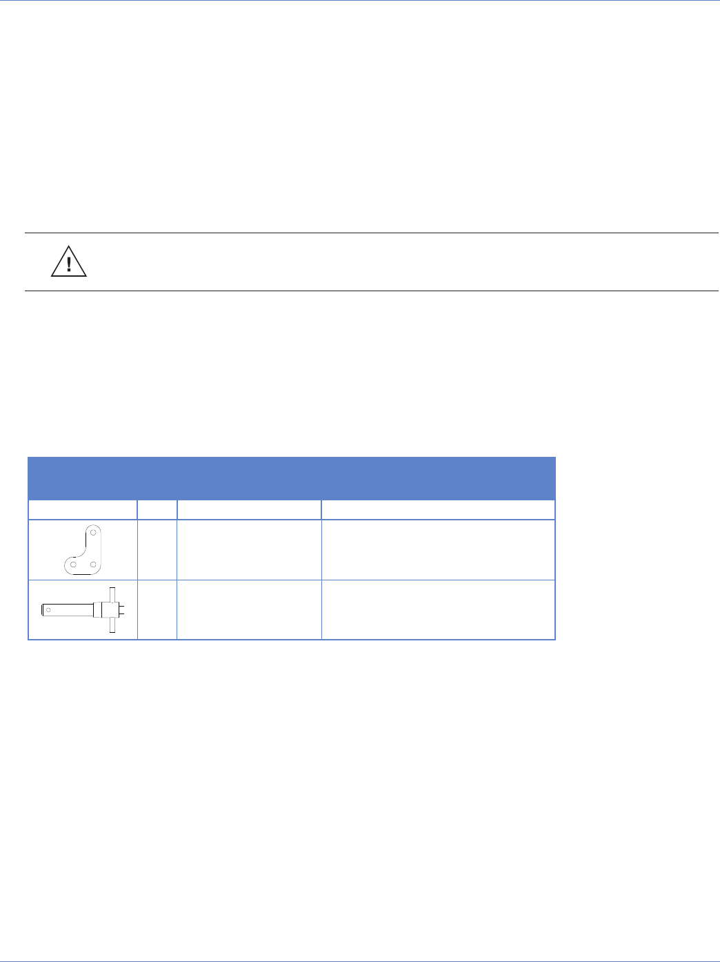
MLK-3D LINK KIT
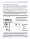
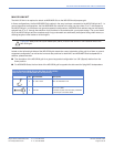
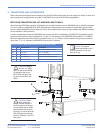
The MLK-3D link kit is required to attach an M3D/M3D-Sub to the MG-3D/M multipurpose grid.
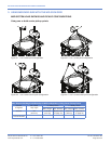
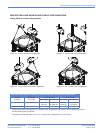
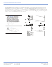
In flown configurations, the first M3D/M3D-Sub cabinet in the array is always connected to the MG-3D/M grid at 0°. In
ground-supported configurations, the first M3D/M3D-Sub cabinet in the array can have from 0° to 5° with respect to
the MG-3D/M grid. In both flown and ground-supported configurations, M3D/M3D-Sub cabinets may be individually
splayed from 0° to 5° through the selection of pin positions in accordance with your system design. The up and down
tilt of the MG-3D/M grid and the complete array hung underneath can additionally be adjusted using chain motors, or
differing lengths of steel cables or chain lengths.
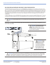
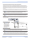
CAUTION: Always use two quick release pins (QRPs) to secure the front MTL-3D transition links to the
MG-3D/M grid.
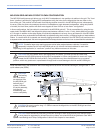
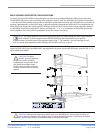
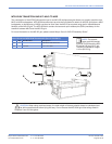
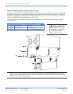
Labels on the left and right sides of the MG-3D/M grid denote the correct orientation of the grid for a flown or ground-
supported configuration, as well as the front and rear positions for both MILO and M3D/M3D-Sub loudspeakers. In
addition, please note that:
The orientation of the MG-3D/M grid for a ground-supported configuration is a 180° (flipped) rotation from the
flown position.
For M3D/M3D-Subs, the front side of the MG-3D/M grid is opposite the side used for flying MILO loudspeakers.
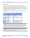
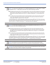
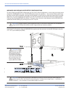
List of Contents: MLK-3D Link Kit (Part 40.132.120.01)
Required for use with M3D/M3D-Sub loudspeaker(s)
Qty Part Number Description
2 61.132.115.02 MTL-3D Transition Link
6 134.007
1/2" x 2.5" QRP*
*Includes lanyard and necessary hardware
to fix the pin to the MG-3D/M


