


MG-3D/M MULTIPURPOSE GRID AND ACCESSORIES
PN: 05.132.036.01 B2
Page 10 of 32
Meyer Sound Laboratories Inc.
www.meyersound.com
T: +1 510 486.1166
F: +1 510 486.8356
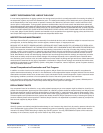
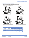
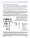
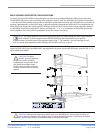
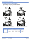
Figure 2.5. 4 to 2 corner point configuration Figure 2.6. 4 to 4 corner point configuration
1
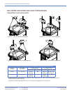
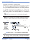
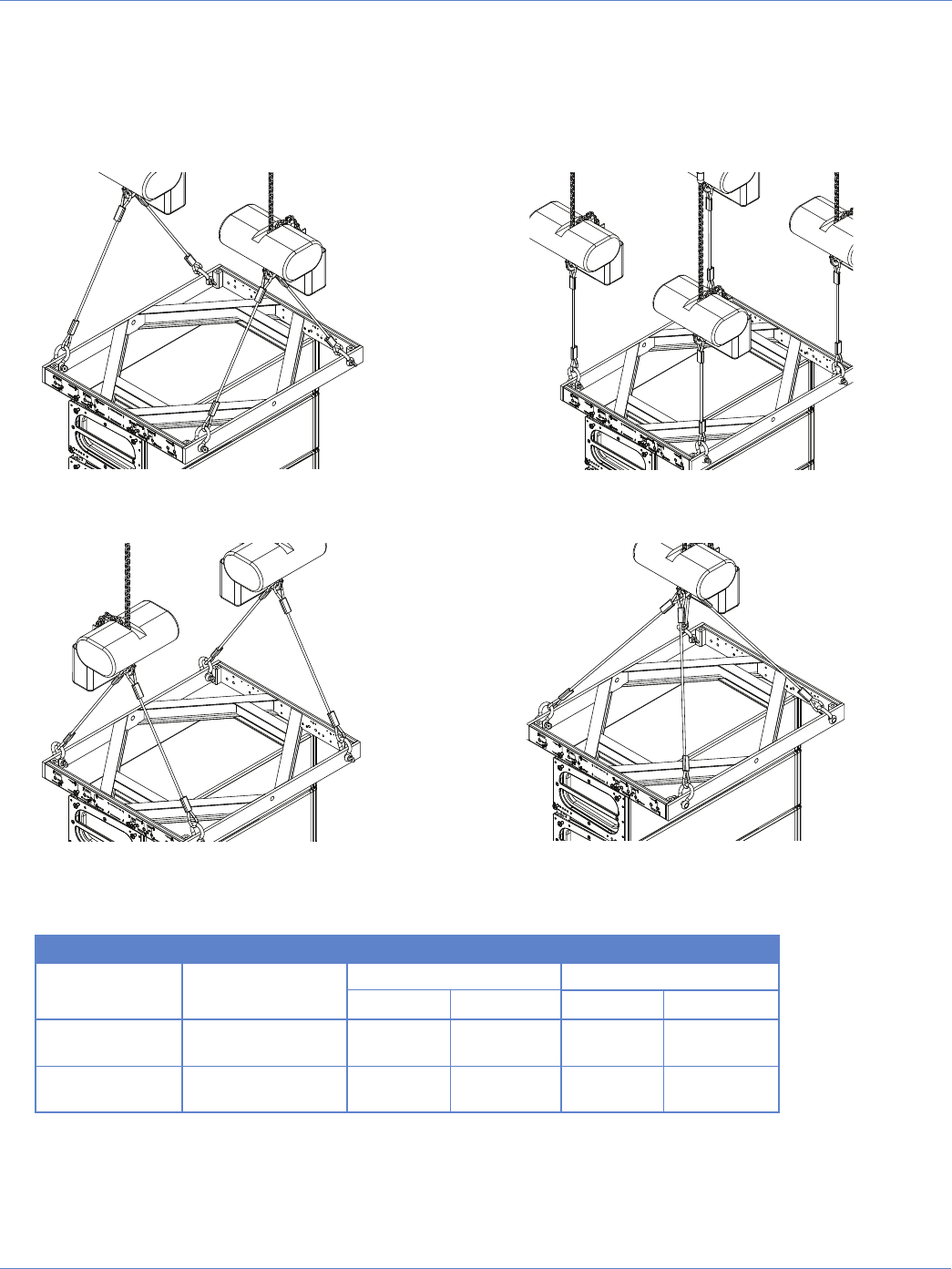
Figure 2.8. 4 to 1 corner point configuration
2
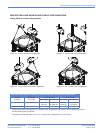
Figure 2.7. 4 to 2 corner cross point configuration
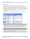
MILO SYSTEM LOAD RATINGS AND PICKUP CONFIGURATIONS
Using all four corner pickup points
Max. Suspended Weight and Quantity of MILO Loudspeakers, Using Corner Pickup Points
Grid Tilt
in Degrees
Min. Bridle
Leg Length
5:1 Safety Factor 7:1 Safety Factor
Max. Weight
Max. Quantity Max. Weight Max. Quantity
±0 to 45 3 ft (915 mm)
2
6000 lbs
(2722 kg)
24
5250 lbs
(2381 kg)
21 (see note 2
on page 11)
±46 to 90 3 ft (915 mm)
2
3570 lbs
(1619 kg)
14 2700 lbs
(1225 kg)
10
1
Please note that the bridle legs are not required in this configuration; the motors can be connected directly to
the MG-3D/M grid using shackles.
2
The minimum bridle leg length for the 4 to 1 corner point configuration is 4 ft (1219 mm).