


Intel® Solid-State Drive DC P3700 Series
Product Specification May 2015
42 330566-009US
Appendix D SMBUS Command Response on
0x6A (NVMe Workgroup Defined)
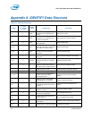
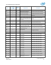
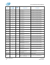
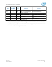
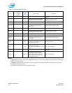
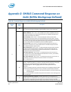
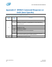
Table 38: Command Response on 0x6A (NVMe Workgroup Defined)
Command
Code
Offset
(byte)
Description
0
00
Length of Status: Indicates number of additional bytes to read before encountering PEC.
This value should always be 6 (06h) in implementations of this version of the spec.
01
Status Flags (SFLGS): This field indicates the status of the NVM subsystem.
SMBus Arbitration – Bit 7 is set ‘1’ after a SMBus block read is completed all the way
to the stop bit without bus contention and cleared to ‘0’ if a SMBus Send Byte FFh is
received on this SMBus slave address.
Drive Not Ready – Bit 6 is set to ‘1’ when the subsystem cannot process NVMe
management commands, and the rest of the transmission may be invalid. If cleared
to ‘0’, then the NVM subsystem is fully powered and ready to respond to management
commands. This logic level intentionally identifies and prioritizes powered up and ready
drives over their powered off neighbors on the same SMBus segment.
Drive Functional – Bit 5 is set to ‘1’ to indicate an NVM subsystem is functional. If
cleared to ‘0’, then there is an unrecoverable failure in the NVM subsystem and the
rest of the transmission may be invalid.
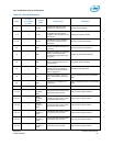
Reset Not Required - Bit 4 is set to ‘1’ to indicate the NVM subsystem does not need
a reset to resume normal operation. If cleared to ‘0’ then the NVM subsystem has
experienced an error that prevents continued normal operation. A controller reset
is required to resume normal operation.
Port 0 PCIe Link Active - Bit 3 is set to ‘1’ to indicate the first port’s PCIe link is up
(i.e., the Data Link Control and Management State Machine is in the DL_Active state).
If cleared to ‘0’, then the PCIe link is down.
Port 1 PCIe Link Active - Bit 2 is set to ‘1’ to indicate the second port’s PCIe link is up.
If cleared to ‘0’, then the second port’s PCIe link is down or not present.
Bits 1-0 shall be set to ‘1’.
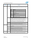
02
SMART Warnings: This field shall contain the Critical Warning field (byte 0) of the NVMe
SMART / Health Information log. Each bit in this field shall be inverted from the NVMe
definition (i.e., the management interface shall indicate a ‘0’ value while the
corresponding bit is ‘1’ in the log page). Refer to the NVMe specification for bit
definitions.
If there are multiple controllers in the NVM subsystem, the management endpoint shall
combine the Critical Warning field from every controller such that a bit in this field is:
Cleared to ‘0’ if any controller in the subsystem indicates a critical warning for that
corresponding bit.
Set to ‘1’ if all controllers in the NVM subsystem do not indicate a critical warning for the
corresponding bit.
03
Composite Temperature (CTemp): This field indicates the current temperature in
degrees Celsius. If a temperature value is reported, it should be the same temperature as
the Composite Temperature from the SMART log of hottest controller in the NVM
subsystem. The reported temperature range is vendor specific, and shall not exceed the