


Intel® Solid-State Drive DC P3700 Series
Product Specification May 2015
24 330566-009US
5.3 Log Page Support
Intel SSD DC P3700 Series supports the following mandatory log pages defined in NVMe 1.0
specification:
Error Information (Log Identifier 01h)
SMART/ Health Information (Log Identifier 02h)
Firmware Slot Information (Log Identifier 03h)
Command Effects Log (Log Identifier 05h)
Note: See NVMe 1.0 version of the specification for the log page content. Additionally, P3700 Series will support
the following vendor unique log pages:
Log Page Directory (Log Identifier C0h)
Read Command Latency Statistics Log (Log Identifier C1h)
Write Command Latency Statistics Log (Log Identifier C2h)
Temperature Statistics (Log Identifier C5h)
Vendor Unique SMART Log (Log Identifier CAh)
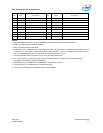
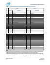
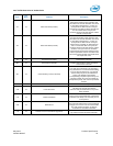
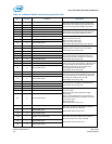
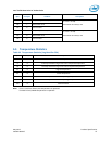
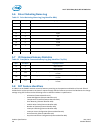
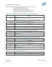
5.4 SMART Attributes
The following table lists the SMART attributes supported by the P3700 Series in accordance with
NVMe 1.0 specification.
Table 18: SMART Attributes (Log Identifier 02h)
Byte
# of
Bytes
Attribute
Description
0
1
Critical Warning: These bits if set, flag various
warning sources.
Bit 0: Available Spare is below Threshold
Bit 1: Temperature has exceeded Threshold
Bit 2: Reliability is degraded due to excessive media
or internal errors
Bit 3: Media is placed in Read- Only Mode
Bit 4: Volatile Memory Backup System has failed
(e.g., enhanced power loss capacitor test failure)
Bits 5-7: Reserved
Any of the critical warning can be tied to
asynchronous event notification. Drive
Health Indicator defined under bytes 3095-
3076 of Identify Controller may still indicate
“healthy” status when the critical warning
flag is set.
1
2
Temperature: Overall Device current temperature in
Kelvin.
For AIC, this reports the NAND temperature,
for 2.5-inch FF, this reports the case
temperature,
3
1
Available Spare: Contains a normalized percentage
(0 to 100%) of the remaining spare capacity
available
Starts from 100 and decrements.
4
1
Available Spare Threshold
Threshold is set to 10%.
5
1
Percentage Used Estimate (Value allowed to exceed
100%)
A value of 100 indicates that the estimated
endurance of the device has been
consumed, but may not indicate a device
failure. The value is allowed to exceed 100.
Percentages greater than 254 shall be
represented as 255. This value shall be
updated once per power-on hour (when the
controller is not in a sleep state).