


Intel® Solid-State Drive DC P3700 Series
Product Specification May 2015
14 330566-009US
2.4 Environmental Conditions
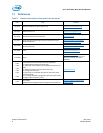
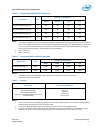
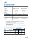
Table 11: Temperature, Shock, Vibration
Temperature
Add-In card form factor
2.5-inch form factor
Temperature
Operating
1
Non-operating
3
Ambient: 0 – 55
o
C / 0 -40
o
C
2
-55–95
o
C
Ambient: 0–35
o
C, Case: 0-70
o
C
Temperature Gradient
4
Operating
Non-operating
30
o
C/hr (Typical)
30
o
C/hr (Typical)
30
o
C/hr (Typical)
30
o
C/hr (Typical)
Humidity
Operating
Non-operating
5–95%
5–95%
5–95%
5–95%
Shock and Vibration
Range
Shock
5
Operating
Non-operating
50 G Trapezoidal, 170 in/s
50 G Trapezoidal, 170 in/s
1,000 G (Max) at 0.5 msec
1,000 G (Max) at 0.5 msec
Vibration
6
Operating
Non-operating
2.17 GRMS (5-700 Hz) Max
3.13 G
RMS
(5-800 Hz) Max
2.17 GRMS (5-700 Hz) Max
3.13 G
RMS
(5-800 Hz) Max
Notes:
1. Operating temperature implies ambient air temperature under defined airflow in Tables 12 and 13.
2. 0-55° C is for airflow from the server towards the card and 0-40° C is for airflow into the server.
3. Please contact your Intel representative for details on the non-operating temperature range.
4. Temperature gradient measured without condensation.
5. Shock specifications assume the SSD is mounted securely with the input vibration applied to the
drive-mounting screws. Stimulus may be applied in the X, Y or Z axis. Shock specification is measured
using Root Mean Squared (RMS) value.
6. Vibration specifications assume the SSD is mounted securely with the input vibration applied to the
drive-mounting screws. Stimulus may be applied in the X, Y or Z axis. Vibration specification is measured
using RMS value.
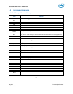
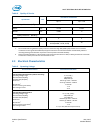
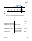
Table 12: Airflow Requirements for Intel SSD DC P3700 Series (Add-In Card)
Airflow
Direction
Unit
Ambient
Temperature
Intel
SSD DC P3700 Series
400GB
800GB
1.6TB
2TB
Towards
the server
LFM
40
o
C
200
300
300
300
Out of the
server
LFM
55
o
C
200
300
300
300
NOTE: For Add-In cards airflow can be for both the directions. Airflow specified is based on approach velocity.