


Intel® Solid-State Drive DC P3700 Series
Product Specification May 2015
4 330566-009US
Figures
Figure 3-1: Intel SSD DC P3700 Series SFF Dimensions ...................................................................................................................... 18
Figure 3-2: Intel SSD DC P3700 Series PCIe Dimensions .................................................................................................................... 19
Figure A-1: LED Location ..................................................................................................................................................................................... 47
Tables
Table 1: Standard Information referenced in this document ......................................................................................................... 8
Table 2: Glossary of Terms and Acronyms .............................................................................................................................................. 9
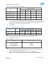
Table 3: User Addressable Sectors........................................................................................................................................................... 10
Table 4: Random Read/Write Input/Output Operations Per Second (IOPS) ........................................................................ 10
Table 5: Random Read/Write IOPS Consistency ................................................................................................................................ 11
Table 6: Sequential Read and Write Bandwidth ................................................................................................................................. 11
Table 7: Latency ................................................................................................................................................................................................ 11
Table 8: Quality of Service ............................................................................................................................................................................ 12
Table 9: Operating Voltage .......................................................................................................................................................................... 12
Table 10: Power Consumption ...................................................................................................................................................................... 13
Table 11: Temperature, Shock, Vibration ................................................................................................................................................ 14
Table 12: Airflow Requirements for Intel SSD DC P3700 Series (Add-In Card) ..................................................................... 14
Table 13: Airflow Requirements for Intel SSD DC P3700 Series (2.5-inch Form Factor) ................................................... 15
Table 14: Product Regulatory Compliance Specifications ............................................................................................................... 15
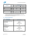
Table 15: Reliability Specifications.............................................................................................................................................................. 16
Table 16: Pin Definition for 2.5-inch Form Factor (8639 connector specification) .............................................................. 20
Table 17: Pin Definition for Add-In Card (Half Height Half Length) Form Factor .................................................................. 22
Table 18: SMART Attributes (Log Identifier 02h) .................................................................................................................................. 24
Table 19: Additional SMART Attributes (Log Identifier CAh) .......................................................................................................... 26
Table 20: Temperature Statistics (Log Identifier C5h) ....................................................................................................................... 27
Table 21: Drive Marketing Name Log (Log Identifier DDh) ............................................................................................................... 28
Table 22: Read/Write Command Latency Log (Log Identifier C1h/C2h) ................................................................................... 28
Table 23: Set Max LBA Setting - Command Dword 11 and Command Dword 12 ................................................................ 29
Table 24: Status Code - Set Max LBA Command Specific Status Values .................................................................................. 29
Table 25: C6h - Set/ Get Power (Typical) Governor Setting – Command Dword 11 ............................................................ 29
Table 26: Status Codes - Power Governor Setting Command Specific Status Values ........................................................ 29
Table 27: D5h – Reset Timed Workload Counters – Command Dword 11 .............................................................................. 29
Table 28: E2h – Set/Get Enable Latency Tracking ............................................................................................................................... 29
Table 29: NVMe Driver Support .................................................................................................................................................................... 30
Table 30: Device Certifications and Declarations ................................................................................................................................. 31
Table 31: Identify Controller .......................................................................................................................................................................... 32
Table 32: Power State Descriptor ................................................................................................................................................................ 36
Table 33: Identify Namespace ....................................................................................................................................................................... 37
Table 34: LBA Format Data Structure ........................................................................................................................................................ 39
Table 35: Vital Product Data Structure (VPD) ......................................................................................................................................... 40
Table 36: Capability List Pointer (Out of Band Temperature Sensor) ......................................................................................... 40
Table 37: Register 0x05 read out format .................................................................................................................................................. 41
Table 38: Command Response on 0x6A (NVMe Workgroup Defined) ....................................................................................... 42
Table 39: Command Response on 0x6A (Intel Specific) ................................................................................................................... 44
Table 40: PCIe ID .................................................................................................................................................................................................. 45
Table 41: LED Functionality ............................................................................................................................................................................ 47