


Intel® Solid-State Drive DC P3700 Series
Product Specification May 2015
36 330566-009US
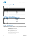
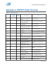
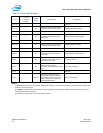
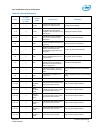
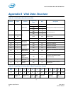
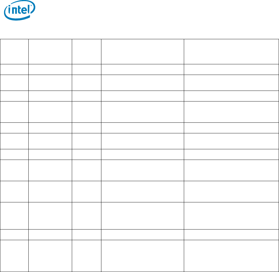
Table 32: Power State Descriptor
Bytes
F = Fixed
V = Variable
X = Both
Default
Value
Interpretation
Description
255-125
Reserved
124-120
F
0h
Indicates the relative write latency
associated with this power state
Relative Write Latency (RWL)
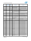
119-117
Reserved
116-112
F
0h
Indicates the relative write
throughput associated with this
power state
Relative Write Throughput (RWT)
111-109
Reserved
108-104
F
0h
Indicates the relative read latency
associated with this power state
Relative Read Latency (RRL)
103-101
Reserved
100-96
F
0h
Indicates the relative read
throughput associated with this
power state.
Relative Read Throughput (RRT)
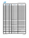
95-64
F
0h
Indicates the maximum exit latency
in microseconds associated with
exiting this power state.
Exit Latency (EXLAT)
63-32
F
0h
Indicates the maximum entry
latency in microseconds
associated with entering this power
state
Entry Latency (ENLAT)
31-16
Reserved
15-00
F
09C4h
Indicates the maximum power
consumed by the NVM subsystem
in this power state. The power in
Watts is equal to the value in this
field multiplied by 0.01
Maximum Power (MP)
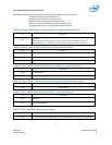
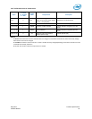
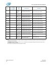
NOTES:
F = Fixed. The content of the word is fixed and does not change. For removable media devices, these values may change when
media is removed or changed.
V = Variable. The state of at least one bit in a word is variable and may change depending on the state of the device or the
commands executed by the device.
X = F or V. The content of the word may be fixed or variable.