36 MHD56037 - Edition 5
25. Install the motor assembly to motor mounting plate using
capscrews (4) and lockwashers (3). Lightly coat capscrew
threads with Loctite
® 242 and torque to 85 ft lbs (115 Nm).
26. On winches with a disc brake install fitting (31) in dump
valve (30) and screw into brake release port. Install vented
fitting (29) in dump valve (30). Install fitting (25) in valve
assembly (260) with elbow (26). Install steel tube (27)
between fitting on dump valve (30) and elbow (26).
Drum Assembly
1. Stand drum in an upright position. Align splines and
carefully lower inboard upright and drum shaft assembly
onto drum (80).
2. Using a ‘C’ clamp, secure inboard flange assembly to drum
flange and set complete assembly in a horizontal position.
3. Clean seal surface and install oil seal (99) in outboard
upright (84) with lip toward drum.
4. Pack bearing (49) with grease and install in outboard upright
(84).
5. Install outboard upright (84) on drum end. Ensure assembly
is kept centered on seal and journal during this step.
6. Install shaft retainer (92). Secure by installing three
capscrews (93). Lightly coat capscrew threads with Loctite
®
242. Torque to 30 ft lbs (41 Nm).
7. Install spacer (91).
8. Apply a light coat of Loctite® 515 sealant to mating surface
of outboard upright (84) and install end cover (95). Secure
using six capscrews (97) and lockwashers (96). Lightly coat
capscrew threads with Loctite
® 242. Torque to 30 ft lbs (41
Nm).
9. Install pipe plug (98) in end cover (95).
10. Install side rails (82 and 83) to uprights (42 and 84) and
loosely secure using capscrews (85) and lockwashers (86).
11. Tap dowel pins (87) into position until flush with side rails.
12. Tighten eight capscrews (85) evenly. Torque to 140 ft lbs
(190 Nm).
13. Mount winch to foundation as described in ‘Mounting’.
Refer to “INSTALLATION” section
on page 8.
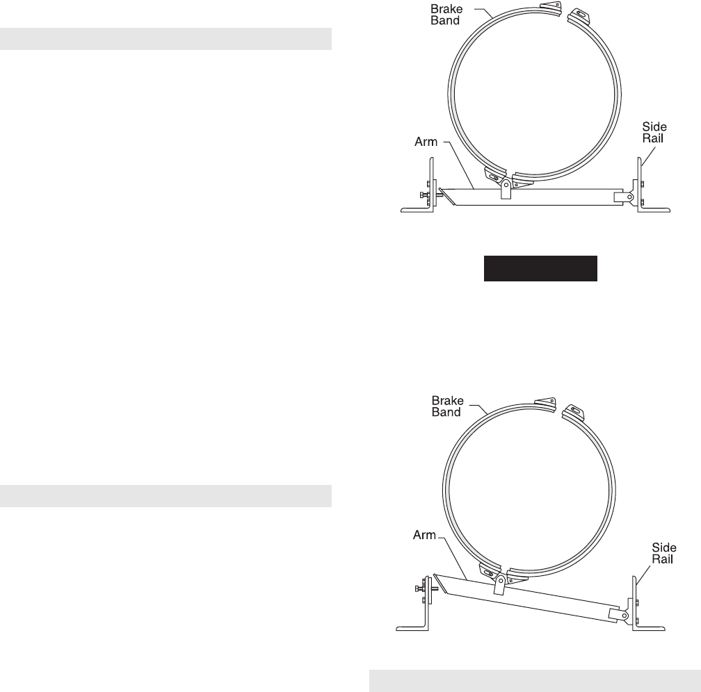
Drum Brake Assembly
Ref. Dwg. MHP0153 on page 48.
1. Install pivot bracket (122) on end of arm (124) with pin (121)
and cotter pin (102). Recessed side of threaded hole must be
toward brake band side.
2. Install connecting link (125) on arm and secure in position
with pin (121), washer (123) and cotter pin (102). Bend ends
of cotter pin over to secure. Assemble connecting link so
curved surface matches contour of brake band.
3. Install halves of brake band (128) to connecting link and
secure with pins (101), (121) and cotter pins (102). Bend
ends of cotter pin over to secure.
4. Lift winch assembly, with a suitable hoist, approximately 6
inches (15 cm) off floor or work bench.
5. Position brake band subassembly around brake diameter on
drum (80) until arm lays at bottom. When positioned, lower
winch.
6. Mount pivot bracket on inside surface of side rail (83) and
secure in position with capscrews (116) and lockwashers
(117).
7. Screw link stud (103) into handle (104) and install handle
(104) in lug on end of brake band (128). Lubricate pivot
points being careful not to get grease on brake band lining.
8. Pull halves of brake band together and install pin (101)
through lug on band (128) and link stud (103) of handle
assembly.
9. Install stop plate (126) on inside of side rail (82) with
capscrew (119) and washer (117). Install adjusting screw
(127) and locknut (120) through side rail (82) and stop plate
(126) until it contacts arm (124). Refer to Dwg. MHP0173
on page 36.
FA5 Band Brake Components
(Dwg. MHP0173)
• On FA5T winches install stop plate (126) at top edge of side
rail (82). Refer to Dwg. MHP0174
on page 36
10. Adjust brake as described under ‘Adjustments’ on page 26
in “MAINTENANCE” section.
FA5T Band Brake Components
(Dwg. MHP0174)
Automatic Drum Brake Actuator Assembly
1. Install bracket (118) on side rail (83) with capscrews (116)
and lockwashers (117).
2. Screw nut (108) and clevis (107) onto cylinder rod.
3. Attach brake lever (105) to brake band (128).
4. Install cylinder (110) so it connects with bracket (118) and
brake lever (105). Use pins (106) and (134), washers (129)
and cotter pins (102) to secure in position.
5. Install dump valve (112), fittings and hose (113) and (115) to
the cylinder (110).
6. Adjust automatic brake as described under ‘Adjustments’ on
page 26 in the “MAINTENANCE” section.


