


MHD56037 - Edition 5 11
Air Lines
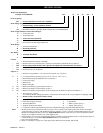
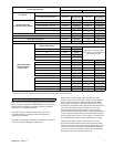
Inside diameter of winch air supply lines must not be less than
sizes shown in Table 4
on page 11. Before making final
connections, all air supply lines should be purged with clean,
moisture free air or nitrogen before connecting to winch inlet.
Supply lines should be as short and straight as installation
conditions will permit. Long transmission lines and excessive use
of fittings, elbows, tees, globe valves etc. cause a reduction in
pressure due to restrictions and surface friction in lines.
Table 4–Minimum Allowable Air Supply Line Sizes
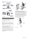
Air Line Lubricator
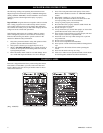
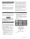
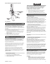
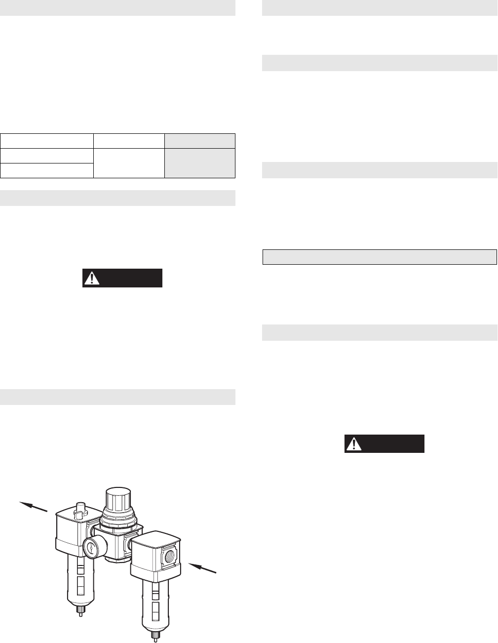
Refer to Dwg. MHP0191 on page 11.
Always use an air line lubricator with these motors. The lubricator
must have an inlet and outlet at least as large as inlet on motor.
Install air line lubricator as close to air inlet on motor as possible.
CAUTION
• Lubricator must be located no more than 10 ft. (3 m) from
motor.
• Shut off air supply before filling air line lubricator.
The air line lubricator should be replenished daily and set to
provide 6 to 9 drops per minute of ISO VG 32 (SAE 10W) oil. A
fine mist will be exhausted from throttle control valve when air
line lubricator is functioning properly.
Air Line Filter
Refer to Dwg. MHP0191 on page 11.
It is recommended that an air line strainer/filter be installed as
close as practical to motor air inlet port, but before lubricator, to
prevent dirt from entering valve and motor. The strainer/filter
should provide 20 micron filtration and include a moisture trap.
Clean the strainer/filter periodically to maintain its operating
efficiency.
(Dwg. MHP0191)
Air Pressure Regulator
If an air pressure regulator is used, install between lubricator and
filter. Refer to Dwg. MHP0191
on page 11.
Moisture in Air Lines
Moisture that reaches the air motor through air supply lines is a
primary factor in determining the length of time between service
overhauls. Moisture traps can help to eliminate moisture. Other
methods, such as an air receiver which collects moisture before it
reaches motor or an aftercooler at compressor that cools air to
condense and collect moisture prior to distribution through supply
lines are also helpful.
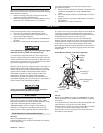
Mufflers
Make sure mufflers are installed in winch exhaust manifold and
control valve exhaust port. An additional muffler is used on
winches equipped with an emergency stop and overload device.
Check mufflers periodically to ensure they are functioning
correctly.
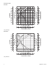
Motor
For optimum performance and maximum durability of parts,
provide an air supply of 90 psig at 700 scfm (6.3 bar/630 kPa at
20 cu. m/m) as measured at motor inlet. The air motor should be
installed as near as possible to compressor or air receiver.
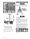
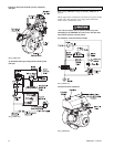
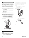
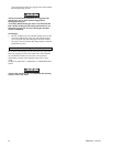
Emergency Stop and Overload System (optional feature)
Refer to Dwg. MHP1492 on page 12.
old style
The air supply line is connected to the shutoff valve which is
connected to the air control valve. When Emergency Stop valve is
activated, a pilot signal is sent to the shut off pilot valve which
directs shutoff valve to cut off air to winch, immediately stopping
all winch movement.
CAUTION
• If winch continues to move (payout load) after shutoff valve
activates, brake(s) are not holding load and need to be
adjusted or repaired.
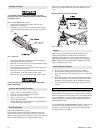
The overload system also activates shutoff valve. When Delta-P
valve senses a preset pressure difference between the two ports,
located on rotary housing, it directs a pilot signal to shutoff pilot
valve activating the shutoff valve. Refer to Dwg. MHP1491
on
page 12.
Model inch mm
FA5
1-1/2 38
FA5T
Air Out
Regulator
Lubricator
Air In
Filter