


MHD56037 - Edition 5 33
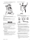
2. Place handle assembly over reverse valve end. Slide handle
will have to be lifted slightly to allow pin to fit into slot in
seal bracket.
3. Secure handle assembly (930) to reverse valve with tab lock
washer (909) and capscrew (901), torque to 15 ft lbs. (21
Nm). Washer (909) has small tab on side, engage with small
hole in handle.
4. Bend tabs of washer (909) over flats of capscrew.
5. Press plug (935) into handle assembly to cover capscrew.
Check control handle movement. Correct any discrepancies.
K5B Control Valve Assembly (old style)
Refer to Dwg. MHP0165 on page 54.
NOTICE
• During assembly align parts using match marks made
during disassembly.
• This valve is no longer available and should be replaced with
K5C2, if necessary.
1. Install seal rings (315) on each end of valve body (316).
2. Install valve body (316) into valve bushing (314).
NOTICE
• Valve bushing (314) is shown exploded for reference ONLY.
3. Install valve body retainer (305) with two capscrews (302)
and lockwashers (96). Torque capscrews to 25 ft lbs (34 Nm).
4. If removed, reinstall spring retaining stud (306) and torque
to 25 ft lbs (34 Nm).
5. Install spring (303) and handle (300) on square shaft of valve
body. Spring (303) ends must straddle spring retaining stud
on throttle handle. Install roll pin (301).
6. Check throttle handle moves fully left and right without
sticking or binding. Throttle handle should center, by spring
force, automatically when released.
K5C2-EX Control Valve Assembly
Refer to Dwg. MHP2180 on page 52.
Reverse Valve Assembly
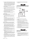
1. Insert reverse valve (943) into bushing (944) with ball slot
oriented UP. Apply grease to ball (916) and insert into ball
slot of reverse valve (943) through bushing (944).
2. Insert bushing (944), reverse valve (943) and ball (916) into
valve housing (917) from exhaust flange side, ensuring that
groove in bushing is aligned with pin (945).
3. Lubricate ‘O’ rings (942) and (722), and place in grooves in
exhaust adapter (723).
4. Lubricate ‘O’ rings (942) and place in grooves in exhaust
flange (955).
5. Secure exhaust adapter with exhaust flange to valve housing
with capscrews (721) and washers (902).
6. Insert ‘O’ ring (941) into seal bracket (939). Lubricate ‘O’
ring (942) and place into groove in seal bracket.
7. Place seal bracket over end of reverse valve. Using finger
pressure, press until seal is seated on reverse valve and seal
bracket is seated on valve housing. Secure with washers
(924) and capscrews (925) and (938).
Pilot Valve Assembly
Follow assembly instructions for K5C2 Control Valve.
Piston Assembly
Follow assembly instructions for K5C2 Control Valve.
Handle Assembly
Follow assembly instructions for K5C2 Control Valve.
Emergency Stop Assembly
1. Insert spring (711) into valve housing (917).
2. Place ‘O’ rings (703) on plunger (707).
3. Insert plunger into valve housing.
4. Screw adapter (706) and E-Stop button (705) into valve
housing.
5. Tighten adapter until snug, do not over tighten.
Overload Valve Assembly
1. Replace ‘O’ rings (703) on plunger (702).
2. Insert plunger (702) with ‘O’ rings in valve housing (917).
3. Replace grommet (701) in cap (700).
4. Install and tighten cap (700) flush to valve housing.
5. Replace piston (712) if appears damaged or worn.
6. Insert ‘O’ ring (713) on piston (712).
7. Replace gasket (714).
NOTICE
• Cover (719) retains springs (718), adjustment nut (717) and
plate (715). Insert capscrews (902) and washers (901) in a
crisscross pattern until tightened evenly.
8. Insert adjusting screw (720), refer to ‘OPERATION’ section
for overload valve adjustment.
9. Secure Control Valve Assembly to intake manifold using
capscrews (951) and washers (949). Use new gaskets (946)
between control valve and manifold.
10. Test control valve for proper operation. Lift slide handle and
move handle all the way in one direction and release hand.
Control handle should return and lock in the neutral position.
Repeat for other direction.
11. Connect brake line.
12. Connect air supply line.
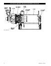
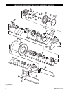
K5B Motor Assembly
Refer to Dwg. MHP2093 on page 44.
1. Assemble throttle valve assembly (260), gasket (248) and
exhaust flange (254) to rotary valve housing (247) using four
capscrews (257) and lockwashers (223). Install two
capscrews (255) and lockwashers (223) that attach exhaust
flange (254) to throttle valve housing.
2. Tighten capscrews (255) and (257) to 25 ft lbs (34 Nm).
Throttle handle should move fully left and right without
sticking or binding, and should center (by spring force)
automatically when released.