


MHD56037 - Edition 5 17
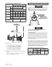
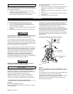
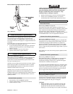
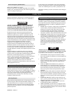
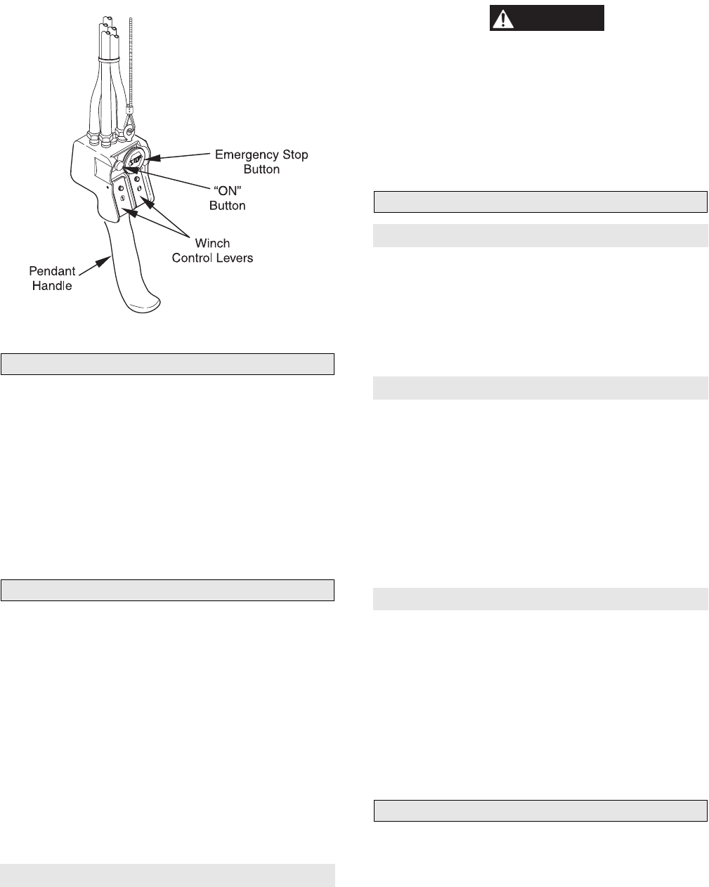
Remote Pendant Emergency Stop Valve Operation
(Dwg. MHP1892)
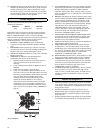
Winch Overload Device (optional feature)
The overload device is integrated into winch air motor control air
system and prevents winch from lifting a load greater than
overload value. Refer to “INSPECTION” section
on page 21. If
an overload is detected, inlet supply air is stopped and winch will
not operate.
If overload device is activated load must be lowered and reduced.
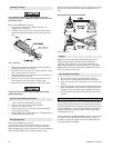
To lower load and reset emergency stop valve:
1. Locate serrated ring directly below emergency stop button.
Rotating serrated ring clockwise, causes emergency stop
button to ‘pop up’.
2. Depress emergency stop valve ‘ON’ button.
3. Operate winch control in payout direction.
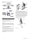
Constant Tension (optional feature)
Refer to Dwg. MHP1865 on page 12.
With auxiliary valve in the NORMAL position, winch provides
normal operation. Placing valve selector in TENSIONING
position allows winch to automatically operate to haul-in slack
wire rope to maintain tension.
Auxiliary valve provides preset air pressure to air motor and disc
brake. This allows brake to be released and winch to overhaul
during TENSIONING operations. In this position, winch will
maintain constant tension on wire rope.
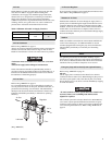
Auxiliary valve is pre-set at zero from the factory. Specific
adjustments must be made in the field. Adjustments can be
modified at anytime to accommodate the load conditions. Refer to
‘Regulator Adjustment’ in the “MAINTENANCE” section for
specific procedure.
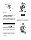
Constant Tension (operation)
1. Place auxiliary valve in NORMAL position.
2. Operate winch normally to position end of load line.
3. Connect load line to load.
WARNING
• Ensure slack load line is taken up by operating winch control
valve with selector in NORMAL position. If selector lever is
placed in TENSION position the winch will immediately
attempt to establish line tension causing line to ‘snap’
resulting in injury or damage to property.
4. Operate winch normally to remove slack from load line.
5. Actuate valve to TENSION position to set winch to
automatically haul-in load line and maintain line tension.
Winch Brakes
Manual Drum Brake
Refer to Dwg. MHP0153 on page 48.
The manual drum brake may be applied by pushing down on
handle (104) and released by pulling up. If handle is pushed down
fully, it should lock in that position and prevent drum rotation,
until released by operator. The brake must be kept properly
adjusted to hold required load. Refer to ‘Adjustments’
on page 26
in “MAINTENANCE” section for adjustment instructions.
Automatic Drum Brake (optional feature)
Refer to Dwg. MHP0153 on page 48.
The automatic drum brake is a spring applied, air released brake
which utilizes an air actuated, spring loaded cylinder (110), that
automatically disengages brake when motor is operated. Air
pressure in cylinder overcomes spring pressure to release brake.
When control valve is placed in neutral position, air in cylinder
(110) is vented and spring automatically engages brake to prevent
drum rotation.
The cylinder clevis (107) must be kept properly adjusted to hold
required load.
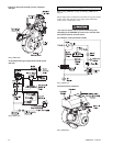
Automatic Disc Brake (optional feature)
Refer to Dwg. MHP0152 on page 46.
The automatic disc brake is a spring applied, air released brake.
Using an air actuated, spring loaded piston (10), the brake
automatically disengages when motor is operated and engages
when throttle is returned to neutral position.
Air pressure ported through brake housing (21) overcomes spring
(9) pressure and moves piston (10) which releases brake. When
control valve is placed in neutral position, air is vented, spring
pressure overcomes air pressure and spring (9) pressure moves
piston, engages brake and prevents drum rotation.
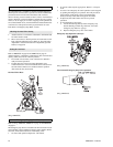
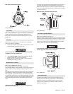
Drum Locking Pin (optional feature)
Refer to Dwg. MHP0155 on page 61.
The drum locking pin is mounted to winch on outboard upright,
opposite motor. It should be engaged if a load is left suspended.
The drum lock is operated by rotating a pin between a shallow
groove (disengaged) and a deep groove (engaged).
To Engage:
1. Rotate drum (80) to align one of the holes in flange with
locking pin (136). Pull out, straight away from outboard
upright, pull rod (140) and rotate counterclockwise 90°,
aligning pin (135) with deep groove in gland (138). Release