


MHD56037 - Edition 5 35
18. Align capscrew and dowel holes and install cover (73). Use a
soft hammer or mallet to carefully tap the cover until flush
with ring gear (72). Apply a light coating of Loctite
® 242 to
capscrew (75) threads and install by hand. Equally tighten
the capscrews in a diametrically opposed pattern to allow for
equal compression of cover onto ring gear (72) and spacer
(71). When cover, ring gear and spacer flanges are flush
torque capscrews to 32 ft lbs (42 Nm).
19. Install dowel pins (74) and tap into position until slightly
below cover flange.
20. Place a bead of Loctite® 515 sealant on surface which mates
with gear carrier. Sealant location should be inside bolt
pattern.
21. Align capscrew and dowel holes and install reduction gear
assembly into drum. Apply a light coating of Loctite
® 242 to
capscrew (45) threads and install capscrews and lockwashers
(46). Torque capscrews to 255 ft lbs (346 Nm).
22. Install two dowel pins (87) and tap into position until
slightly below gear carrier flange.
23. Apply thin coat of Loctite® 609 to outside of seal (43) and,
with seal lip facing out, install in gear carrier (47).
Winch Assembly
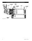
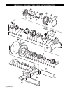
Refer to Dwg. MHP0157 on page 40.
1. Clean both mating surfaces on inboard upright (42) and
install drum shaft (41) through bore aligning dowel pin
holes.
2. Install dowel pins (40) flush or slightly below surface of
drum shaft (41).
3. Install eight capscrews (39). Lightly coat capscrew threads
with Loctite
® 242 and torque to 80 ft lbs (108 Nm).
4. Press bearing (37) onto shaft (35). Lightly coat inner bearing
race bore with Loctite
® 609. Install retainer ring (38).
5. Install shaft and bearing into drum shaft (41) so smaller
splined end enters first. Install retainer ring (36) in bore of
drum shaft (41).
Instructions 6 through 17 cover winches with a disc brake.
For winches without a disc brake skip to instruction 18.
6. Install spacer (34) on shaft (35). Install splined hub (19) so
splined side on outside diameter goes on first. Install
capscrew in locking ring (18) and place on shaft (35).
Maintain pressure on locking ring to keep it against splined
hub (19) and tighten capscrew in locking ring (18).
7. Lubricate and install ‘O’ ring (33) on hub of drum shaft.
8. Install brake housing (21) on drum shaft (41) being careful
not to damage ‘O’ ring (33).
9. Position brake housing so brake port is in the 2 o’clock
position (as viewed from the motor end). Install drain plug
(24) in brake housing at the 6 o’clock position.
10. Install fitting (22) and breather (23) in the top of the brake
housing.
11. Lubricate friction plates (16) with a light motor oil (refer to
‘Recommended Lubricants’
on page 19 in
“LUBRICATION” section). Install friction plates (16) and
drive plates (17) in brake housing. Begin with a friction plate
then alternate with drive plates between friction plates.
Ensure splined teeth mesh. Do not force plates into place
during installation.
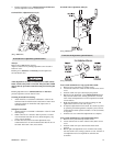
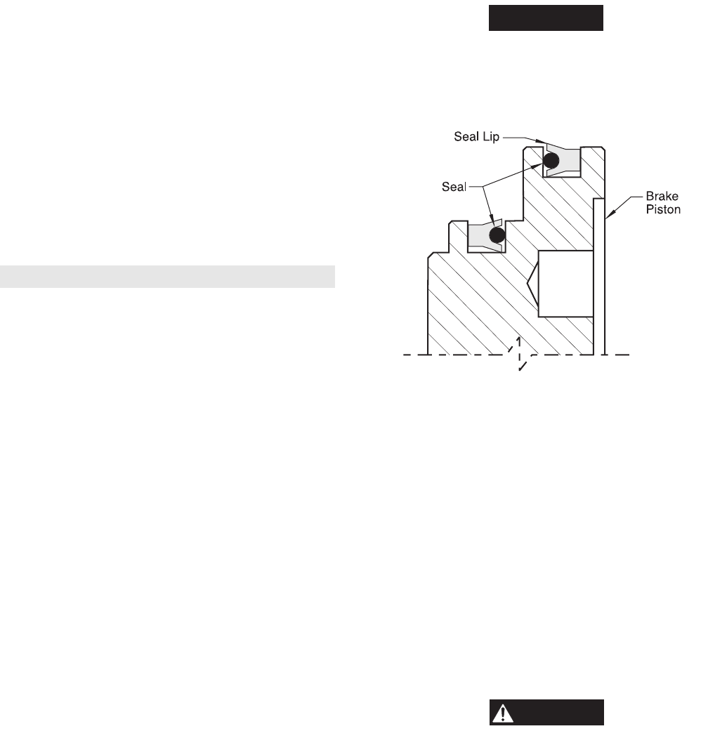
12. Lubricate and install seals (11) and (12) in brake piston (10)
grooves so seal lips face each other. Do not overstretch seals
during this procedure. Refer to Dwg. MHP0139
on page 35.
13. Install brake piston assembly in brake housing so stepped
side enters first. Gently tap into position using a soft mallet
until seated.
14. Install one brake spring (9) in each brake spring holes.
15. Lubricate and install ‘O’ ring (33) in groove on brake
housing (21).
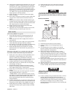
NOTICE
• ‘O’ ring, item 33 listed in step 15 refers to part number 51460
as shown on disc brake Dwg. MHP0152
on page 46. This part
must be placed between brake housing (21) and motor adapter
(6).
Brake Seal Installation
(Dwg. MHP0139)
17. Install brake reaction plate (8) in motor adapter.
18. Install seal adapter (15) in mounting flange (216), if
required.
19. Two threaded holes in motor adapter (6) are centered
between mounting bolt holes. Install motor adapter with
these two holes in 6 o’clock position.
20. Secure motor adapter with eight capscrews (1) using
Loctite
® 242. Torque to 125 ft lbs (170 Nm). On winches
with a disc brake install capscrews evenly to compress brake
springs, and torque to 80 ft lbs (108 Nm). Do not allow plate
to become cocked. Evenly hand tighten all capscrews before
applying final torque.
21. On disc brake equipped winches install shaft extender (7) on
end of shaft (35). On winches without disc brake install seal
sleeve (14) on shaft (35).
22. Lubricate and install ‘O’ ring (5) in groove on motor adapter.
23. Ensure seal adapter (15) and oil seal (2) are installed in bore
of motor assembly. Seal lip must face into motor assembly.
WARNING
• The air motor weighs approximately 260 lb. (118 kg).
Adequately support air motor while installing motor
mounting capscrews.
24. If motor assembly is being mounted with winch in a vertical
position, install one short bolt and nut to keep motor
mounting flange from dropping off. Lower motor assembly
carefully onto the shaft. Position throttle assembly at the top.
Be careful not to damage oil seal (2). When correctly
positioned remove bolt and nut and lower motor assembly the
remaining distance.