


28 MHD56037 - Edition 5
5. Hold cam adjustment screw in position (venting air) and
tighten red setscrew.
6. If required, adjust payout limit switch. Test winch set points
by operating winch through three complete cycles to ensure
consistent limit switch operation within +/- 2 feet (2/3 metre)
of set points.
7. Install access cover when final adjustments are complete.
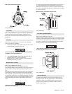
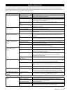
Constant Tension Adjustment (optional feature)
Refer to Dwg. MHP1865 on page 12.
The regulator is preset at 0 psig (0 bar/0 kPa), therefore requires
adjustment when winch is installed. To adjust for specific load
applications, regulator pressure may be adjusted to increase or
decrease tension setting.
Regulator gauge and regulator are accessible through cover.
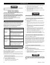
WARNING
• When adjusting regulator, ensure winch control lever is
locked in neutral position and tension selector lever is in the
NORMAL position.
• Winch supply air is NOT shut off during regulator
adjustments. To prevent accidental winch operation, allow
only a single person, trained in safety, operation and
maintenance of this product, to conduct regulator
adjustments.
Regulator Adjustment Procedure:
Refer to Dwg. MHP1865 on page 12.
1. Attach test load of desired weight to load line, or connect
load line to scale.
WARNING
• Ensure load line is connected to load and excessive slack is
taken up before activating auxiliary valve. When activated,
auxiliary valve will automatically engage and winch will
operate at full speed to set tension on load line.
2. With winch control valve remove all slack from load line.
Setting with test load:
1. Actuate auxiliary valve to TENSIONING position. Winch
should operate, causing load line to become taut. To increase
tension, turn regulator knob clockwise until load begins to
rise. Turn regulator knob counterclockwise a minimum of ¼
turn, or until load is balanced (does not raise or lower). Note
pressure indicated on gauge for future setting reference.
Setting with scale:
1. Actuate auxiliary valve to TENSIONING position. Winch
should operate, causing load line to become taut. To increase
tension, turn regulator knob clockwise until scale indicates
desired tension. Note pressure indicated on gauge for future
setting reference.
Disassembly
General Disassembly Instructions
The following instructions provide necessary information to
disassemble, inspect, repair, and assemble winch. Parts drawings
are provided in parts section. If a winch is being completely
disassembled for any reason, follow the order of topics as they are
presented. It is recommended that all maintenance work on winch
be performed in a clean dust free work area.
In the process of disassembling winch, observe the following:
1. Never disassemble winch any further than is necessary to
accomplish needed repair. A good part can be damaged
during the course of disassembly.
2. Never use excessive force when removing parts. Tapping
gently around perimeter of a cover or housing with a soft
hammer, for example, is sufficient to break the seal.
3. Do not heat a part with a flame to free it for removal, unless
part being heated is already worn or damaged beyond repair
and no additional damage will occur to other parts.
In general, winch is designed to permit easy disassembly and
assembly. The use of heat or excessive force should not be
required.
4. Keep work area as clean as practical, to prevent dirt and other
foreign matter from getting into bearings or other moving
parts.
5. All seals and ‘O’ rings should be discarded once they have
been removed. New seals and ‘O’ rings should be used when
assembling winch.
6. When grasping a part in a vise, always use leather-covered
or copper-covered vise jaws to protect the surface of part and
help prevent distortion. This is particularly true of threaded
members, machined surfaces and housings.
7. Do not remove any part which is a press fit in or on a
subassembly unless removal of that part is necessary for
repairs or replacement.
8. When removing ball bearings from shafts, it is best to use a
bearing puller. When removing bearings from housings,
drive out bearing with a sleeve slightly smaller than outside
diameter of bearing. The end of sleeve or pipe which
contacts bearing must be square. Protect bearings from dirt
by keeping them wrapped in clean cloths.
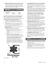
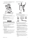
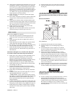
Winch Disassembly
Refer to Dwg. MHP0157 on page 40, MHP2093 on page 44 and
MHP0152 on page 46.
1. Remove wire rope from drum.
2. Operate winch to position reduction gear drain plug at it’s
lowest position.
3. Relieve pressure in air lines by operating winch control
several times after air supply has been turned off.
WARNING
• Shut off, bleed down and disconnect air supply line before
performing any disassembly procedures.
4. Disconnect and tag air lines.
5. Remove winch from its mounting and take to a suitable work
area before beginning disassembly.
6. Remove lower case drain plug (225) on K5B motor housing
(217) and allow oil to drain into a suitable container. Loosen
fill cap (210) to vent motor housing.