


MHD56037 - Edition 5 29
7. Drain oil from reduction gear assembly by removing one
plug (48) when positioned at it’s lowest point, and one plug
(48) from it’s highest point to vent. Refer to Dwg. MHP0140
on page 20 in “LUBRICATION” section. If winch is
equipped with a drum band brake elevate winch outboard
end (opposite from motor end) to prevent draining oil from
contaminating brake band lining.
8. For winches with a disc brake remove pipe plug (24) in
brake housing (21) to drain brake oil.
9. Remove drum band brake, drum guard and any other
externally mounted winch attachments.
WARNING
• The K5B air motor weighs approximately 260 lb. (118 kg).
Adequately support air motor before removing motor
mounting capscrews.
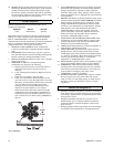
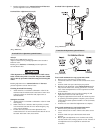
10. Remove capscrews (4) and lockwashers (3) securing motor
assembly to motor adapter (6). Using a hoist to support
motor, pull motor straight away from winch. Reference the
applicable Motor Disassembly section if motor disassembly
is required.
Instructions 11 through 17 apply only to winches with a disc
brake.
11. Alternately and evenly loosen eight capscrews (1) until brake
spring tension has been released. Remove capscrews and
motor adapter (6).
12. Remove brake housing (21). If brake housing sticks, tap it
with a soft faced hammer until parts separate.
Note position of all brake parts for reassembly.
13. Remove three friction plates (16) and two drive plates (17).
14. Remove springs (9) from brake piston (10).
15. Remove brake piston (10) from brake housing (21). Tap
lightly with a plastic mallet to separate parts if necessary.
16. Remove seals (11) and (12) from brake piston (10).
17. Loosen capscrew in collar (18) and slide collar from shaft
(35) with splined hub (19) and spacer (34) from shaft (35).
18. Remove retainer ring (36) from bore of drum shaft (41).
19. Pull shaft and bearing assembly from drum shaft (41).
20. Support drum (80) and remove capscrews (39) from drum
shaft (41). Pry drum shaft (41) from inboard upright (42).
21. Remove capscrews (85) and lockwashers (86) which secure
side rails (82) and (83) to inboard upright (42). Drive out
dowel pins (87).
22. Remove inboard upright (42).
23. Remove end cover (95), capscrews (97) and lockwashers
(96) from outboard upright (84).
24. Remove capscrews (93) and shaft retainer (92) from drum
(80).
25. Remove drum and reduction gear assembly.
26. Remove remaining capscrews (85) and lockwashers (86)
which attach side rails (82) and (83) to outboard upright
(84). Drive out dowel pins (87).
27. Remove bearing (49) and seal (99) from outboard upright
(84).
28. Remove capscrews (45) and lockwashers (46) securing gear
carrier (47) to drum (80).
29. Install two 3/4 inch - 10 NC x 3 inch long capscrews into
threaded holes in outer bolt pattern ring of gear carrier (47).
Use these capscrews to break seal. Remove reduction gear/
gear carrier assembly from drum (80).
To disassemble reduction gear refer to Reduction Gear
Disassembly section.
Manual or Automatic Drum Brake Disassembly
Refer to Dwg. MHP0153 on page 48.
1. Automatic Brake
a. Disconnect and remove hose, fittings and dump valve
(112) from cylinder (110).
b. Remove cotter pin (102) and pin (101) from link stud
(103) and brake band (128).
c. Remove cotter pin (102), washers (129) and pin (106).
Separate clevis (107) from brake lever (105).
d. Remove cotter pin (102) and pin (134). Remove
cylinder (110) from bracket (118).
2. Manual Brake:
a. Remove cotter pin (102) and pin (101) from handle
(104) then remove handle (104) from brake band (128).
3. Remove capscrews (119), lockwashers (117) and stop plate
(126).
4. Use a hoist to raise winch approximately 6 inches (15 cm).
Separate brake band (128) halves and rotate brake band
assembly slowly until it can be removed from drum (80).
5. Remove cotter pins (102) and pins (121) so brake band
halves (128) can be removed from arm (124). Lower winch
when brake band assembly has been removed.
6. Refer to ‘Brake Lining Instruction Sheet’ (Form
MHD56142) for brake lining replacement procedures.
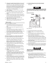
Reduction Gear Disassembly
Refer to Dwg. MHP0157 on page 40.
NOTICE
• It is important to maintain a clean work area when reduction
gear assembly is disassembled.
1. Place reduction gear assembly on a clean work bench such
that end containing bearing (49) is down.
2. Remove capscrews (75) and pry off cover (73).
3. Remove ring gear (72), planet assembly (67) and sun gear
(69).
4. Remove and discard ‘O’ rings (62) from ring gear (72).
5. Remove four pins (74) from between cover (73) and spacer
(71) and store in a safe place.
6. Remove spacer (71), ring gear (63) and sun gear (66).
7. If required, remove thrust plate (55) from sun gear (66).
Remove and discard ‘O’ rings (62) from ring gear (63).
8. Remove capscrews (60) from input housing (59). Separate
input housing from gear carrier (47).
9. Remove planet assembly (58).
10. Remove ring gear (53). Remove three dowel pins (52) from
between input housing (59) and gear carrier (47) and store in
a safe place.
11. Remove and discard ‘O’ rings (51) from ring gear (53).
12. Remove retainer ring (57) and sun gear (56). If required,
remove thrust plate (55) from sun gear.
13. Remove planet assembly (54).
14. Remove retainer ring (50) and bearing (49) from gear carrier
(47).