


MHD56037 - Edition 5 31
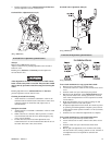
Piston Removal
1. Remove capscrews (901) and washers (902) from piston
cover (919). Remove cover and discard gasket (918).
2. Remove capscrews (901) and washers (902) from poppet
cover (903). Remove cover and discard gasket (904).
3. Remove the following items from housing poppet bore:
spring (905), poppet cap (906) and poppet seal (907).
4. From poppet side, push piston (922) out of housing. Remove
‘O’ rings (921) and (923) and discard.
Pilot Valve Removal
NOTICE
• For easier removal it is recommended to use IR pilot valve
tool (920). This must be purchased separately.
If pilot valve is not damaged it is not necessary to disassemble
completely.
1. Remove plug (912).
2. Remove pilot valve assembly (910) as an assembly.
3. Discard and replace pilot valve assembly (910) if necessary.
K5B Control Valve Disassembly (old style)
Refer to Dwg. MHP0165on page 54.
NOTICE
• Match mark throttle valve parts to ensure proper re-
assembly.
1. Remove two capscrews (302) and lockwashers (96) that hold
the valve body retainer (305).
2. Mark square end on valve body (316) and handle (300) to
ensure correct orientation during reassembly.
3. Drive out pin (301) and remove handle (300).
4. Make note on how spring (303) is positioned before
removing it. Pull valve body (316) out of valve bushing
(314) while disconnecting spring (303).
5. Remove seal rings (315) from valve body (316).
6. Check parts for score marks or wear.
7. Measure clearance between valve bushing (314) and valve
body (316). Clearance between valve bushing and valve
body should not exceed 0.002 inch (0.05 mm) or excessive
air leakage will occur.
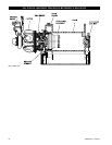
K5C2-E Control Valve Disassembly
Refer to Dwg. MHP 2180 on page 52.
Handle Removal
Follow disassembly instructions for K5C2 Control Valve.
Reverse Valve Removal
1. Remove capscrews (938), (925) and washers (924) from seal
bracket (939). Remove seal bracket from housing. Remove
and discard ‘O’ rings (941) and (942).
2. Remove capscrews (721) and washers (902) from exhaust
flange (955) and exhaust adapter (723). Remove and discard
‘O’ rings (942) and (722).
3. Move reverse valve (943) out exhaust flange side of housing
until ball (916) is visible on reverse valve. Allow ball (916)
to drop out of bushing (944) and remove ball (916).
4. Remove bushing (944) out exhaust flange side of housing.
NOTICE
• Dowel pin (945) allows the bushing to be removed only from
the exhaust flange side of housing. Ball (916) retains reverse
valve (943) in bushing (944).
• Do not remove reverse valve (943), bushing (944) and ball
(916) at the same time, damage may occur to bushing.
Piston Removal
Follow disassembly instructions for K5C2 Control Valve.
Pilot Valve Removal
Follow disassembly instructions for K5C2 Control Valve.
Emergency Stop Removal
1. Remove adapter (706) and E-Stop button (705).
2. Remove plunger (707). Remove and discard ‘O’ rings (703).
3. Pull spring (711) out of valve housing and discard.
Overload Valve Removal
1. Remove cap (700). Remove and discard grommet (701).
2. Pull out plunger (702), remove and discard ‘O’ rings (703).
3. Remove capscrews (901) and washers (902) from cover
(719) underneath valve housing.
NOTICE
• Cover (719) retains spring (718). To remove capscrews (901)
and washer (902) unscrew in a crisscross pattern.
4. Remove adjusting screw (720).
Cleaning, Inspection and Repair
Clean all winch component parts in solvent (except drum brake
bands and disc brake friction plates). The use of a stiff bristle
brush will facilitate removal of accumulated dirt and sediments on
housings, frame and drum. If bushings have been removed it may
be necessary to scrape old Loctite
® from bushing bores. Dry each
part using low pressure, filtered compressed air. Clean drum
brake band using a wire brush or emery cloth. Do not wash drum
brake band in solvent. If drum brake band lining is oil soaked, it
must be replaced.
Inspection
All disassembled parts should be inspected to determine their
fitness for continued use. Pay particular attention to the
following:
1. Inspect all gears for worn, cracked, or broken teeth.
2. Inspect all bushings for wear, scoring, or galling.
3. Inspect shafts for ridges caused by wear. If ridges caused by
wear are apparent on shafts, replace shaft.
4. Inspect all threaded items and replace those having damaged
threads.