


5
•
Check the operator manufacturer’s specification to ensure that
the operator is proper for the cycles per hour, size and type of
gate.
•
USE EXTREME CAUTION WHEN WORKING NEAR THE
BELTS AND PULLEYS when the operator cover is removed.
Apply power to the operator only when instructed to do so.
•
Before activating the "timer to close" option of the HDSWG
1000, ENSURE THE PERSONAL ENTRAPMENT DEVICES
(operator reversing feature, edges, photocells) ARE
OPERATING and install VEHICLE DETECTOR LOOPS
AND VEHICLE DETECTORS for protection of user vehicles.
Read the manual for information on the installation of these
devices. IF VEHICLE DETECTOR LOOPS HAVE BEEN
INSTALLED TO PREVENT THE GATE FROM CLOSING
ON A VEHICLE, INSTRUCT THE USER TO
PERIODICALLY CHECK THE OPERATION OF THE
DETECTORS.
•
Make sure that the gate moves freely, all hinges are in good
working order, the gate does not bind in any manner and the
gate swing area is clean and free of irregularities.
•
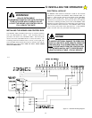
When the HDSWG 1000 Control Box cover is removed and
the small metal cover from terminals 14, 15, 16, 17 and 18 is
also removed, 115 Volts will be exposed AS LONG AS THE
MAIN POWER SWITCH IS ON. EVEN IF THE RED
POWER LIGHT IS NOT LIGHTED, 115 VOLTS AC MAY
STILL BE PRESENT ON THESE TERMINALS. NEVER
LEAVE THE INSTALLATION WITH THESE COVERS
REMOVED.
•
DO NOT INSTALL THE OPERATOR UNTIL ALL GATE
PROBLEMS HAVE BEEN CORRECTED.
•
DO NOT consider the built in sensitivity overload as the
primary defense system. Consider all options in the gate
system design.
•
DO NOT connect any auxiliary equipment to the HDSWG
1000 (detectors, card readers, etc.) until the gate operator and
all its functions are fully tested. Only connect one device at a
time and ensure its proper function(s) before moving on to the
next device.
•
Install the operator on the inside of the property/fence line.
DO NOT install an operator on the public side of the fence line
or gate. Outward swinging gates should not open into public
areas.
•
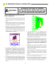
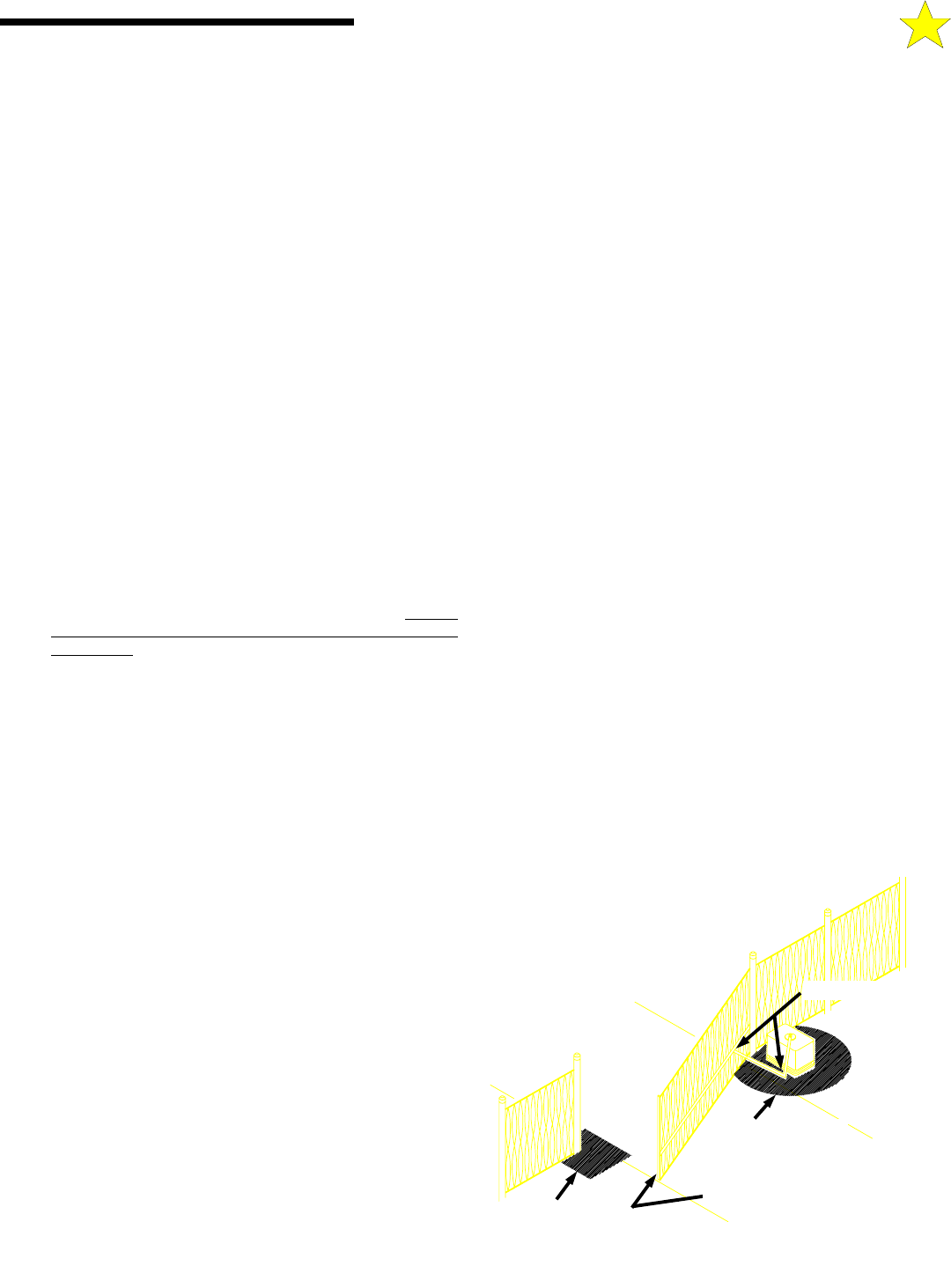
IDENTIFY THE ENTRAPMENT ZONES AND PINCH
POINT AREAS PER FIGURE 4. Design the gate installation
to minimuze the risk of entrapment in these areas. Install
additional safety equipment such as four wire edges and
photocells to further minimize risk. All entrapment zones are
required to be protected.
•
AS THE INSTALLER YOU ARE RESPONSIBLE
FOR:
1. ASSURING THAT THE OWNER/END USER OF THE
SYSTEM UNDERSTANDS ITS BASIC OPERATION
AND SAFETY FEATURES. IN PARTICULAR, BE
SURE THE OWNER/END USER UNDERSTANDS THE
LOCATION AND OPERATION OF A MANUAL
DISCONNECT (WHERE PROVIDED) OR HOW TO
OPERATE THE GATE MANUALLY.
2. POINTING OUT TO THE OWNER/END USER OF
THE GATE SYSTEM THAT CHILDREN OR PETS
ARE NOT ALLOWED TO PLAY ON OR NEAR THE
GATE, FENCE OR ANY PART OF THE SYSTEM,
AND THAT THE SAFETY INSTRUCTIONS SUPPLIED
WITH THIS OPERATOR AND THEIR
IMPLEMENTATION ARE THE RESPONSIBILITY OF
THE OWNER/END USER.
3. LEAVING THE INSTALLATION AND
MAINTENANCE MANUAL FOR THIS OPERATOR AS
WELL AS ANY ADDITIONAL SAFETY
INFORMATION SUPPLIED WITH THIS OPERATOR
OR OTHER COMPONENTS OF THE GATE SYSTEM
WITH THE OWNER/END USER.
4. NOT PLACING IN SERVICE THIS OPERATOR IF
YOU HAVE ANY QUESTIONS ABOUT THE SAFETY
OF THE GATE OPERATING SYSTEM. CONSULT
THE OPERATOR MANUFACTURER.
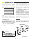
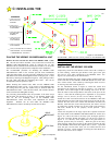
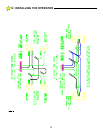
SWING GATE ENTRAPMENT PROTECTION
Use the following illustration to minimize the risk of injury in your
design of the swing gate operator system.
Entrapment Zones: Design in personal entrapment protection
devices to protect people from entrapment in the zones shown
below.
Pinch Points: Use protective measures (guards, padded edges,
etc.) to protect people from the pinch points shown below.
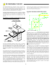
THE CONCRETE PAD
PINCH POINTS
ELECTRIC GATE EDGE
ENTRAPMENT
ZONE
ENTRAPMENT
ZONE
104932
Figure 4
A:
IMPORTANT INSTALLATION NOTES