


15
The Limit Switch contacts of the two Bi-Parting units need to be
wired in series. Both limit switch contacts must be closed before a
connection is made to the limit switch input at the Control Box to
stop the motors at the Open or Closed position.
The operation of the Bi-Parting installation is as follows: After
receipt of a command to open, both units will begin to open
together. The first gate to reach its open position will be
stopped by the mechanical stop. Its motor will continue to run.
The Torque Limiter will be adjusted to slip when the stop is
encountered with the motor still running. The limit switch
contact on this first unit is adjusted to close at this position. The
second gate has not reached its fully open position. Its limit
switch will be still open and no command will be given to the
limit switch input at the terminal board until the gate has reached
the maximum open position and the open limit contact is closed.
Now, a contact will be made to the limit switch input at the
terminal board through both limit switch contacts. Both motors
will be turned off.
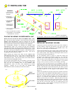
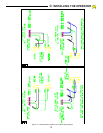
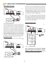
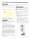
A wiring schematic of the Bi-Parting installation is shown in
Figure 13. It is important this schematic be followed closely and
that the color codes at the MECHANICAL UNITS and the
CONTROL BOX be followed exactly. Most of the difficulties
encountered with Bi-Parting installations are due to the wiring
instructions not being followed.
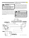
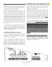
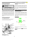
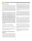
ACCESSORY EQUIPMENT HOOK-UP
All accessory equipment is connected to the 13 terminal barrier
strip located at the bottom of the HDSWG 1000 Control Box
(Backplane). To expose this terminal strip and the Backplane,
remove the cover on the Control Box.
There are 7 command inputs (#6 through #12) available to the
installer on the HDSWG 1000 in a addition to 2 commons. To
trigger any of these inputs, a switch or relay closure to the
common terminal for a duration longer than 100 milliseconds
and of a resistance of less than 100 ohms is necessary. Three of
the inputs, HOLD OPEN, REVERSING & STOP, can be
continuous commands as noted below. Labels on the Backplane
identify the function of each of the terminals on the barrier strip.
See the INPUT COMMANDS Reference Chart on page 18
related to each terminal number on the barrier strip for an
explanation of each of the inputs.
The HDSWG 1000 has an auxiliary transformer mounted in the
Control Box to power accessory equipment. This is a Class II
transformer and is equipped with an internal fusible link. If this
link is "blown" the transformer must be replaced. The
transformer is powered at all times that the HDSWG 1000 main
power switch is ON. It is not fused by any of the fuses on the
Backplane. The maximum power that can be supplied by this
Auxiliary transformer is 20VA or about 1 Ampere at 24VAC
.
This is usually sufficient to supply most accessory equipment
such as a radio receiver, loop detector or card or key pads.
IF THE AUXILIARY TRANSFORMER IS USED TO POWER
A RADIO RECEIVER, NO OTHER EQUIPMENT MAY BE
CONNECTED TO THE AUXILIARY TRANSFORMER. When
a radio receiver is connected to the transformer for power,
one end of the receiver relay must be connected to the
common terminal on the barrier strip. This will effectively
ground one side of the auxiliary transformer even if it is a "4
wire" receiver---in most cases. Many other auxiliary devices,
such as card readers and key pads, (using bridge rectifiers)
require that both sides of the transformer supplying power
be "floating" and not grounded.
FAILURE TO OBSERVE
THIS RESTRICTION WILL DAMAGE THE ADDED
DEVICE.
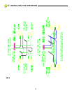
WIRING RADIO RECEIVERS TO THE TERMINAL STRIP
Radio Receivers may be either 3 wire (terminal) or 4 wire units.
THE 4 WIRE VERSION OF THE RECEIVER IS PREFERRED
SINCE NO ADDITIONAL CONNECTIONS TO THE
RECEIVER WILL BE REQUIRED.
104889
Figure 14: Termminal Strip
C:
INSTALLING THE OPERATOR