


19
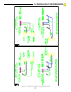
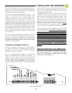
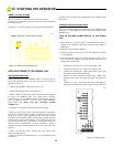
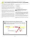
SETTING THE LIMIT SWITCHES
RIGHT-HANDED OPERATION
With the cover removed from the HDSWG 1000 MECHANICAL
UNIT, and the arm connected to the gate as well as to the HDSWG
1000 Operator, position the gate at its fully closed position.
Indentify the lower Limit Switch. Loosen the clamping nut on the
Limit Switch Cam for the lower Limit Switch. Rotate the cam on
the output shaft until it engages the Limit Switch and an audible
“click” is heard. Repeat this several times until you are confident
that the position of the cam is such that the Limit Switch is just
closed. Carefully tighten the nut on the Limit Switch Cam. Snug the
set screw on the cam against the output shaft to protect the cam from
accidental movement. Open the gate to its fully open position.
Repeat this procedure for the upper Limit Switch and Cam. (See
Figure 18.)
SETTING THE LIMIT SWITCHES
LEFT-HANDED OPERATION
For a LEFT HAND installation, the cam positions will be reversed.
The Upper Limit Switch will be the close Limit Switch and the
Lower Limit Switch will be the Open Limit Switch.
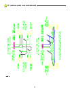
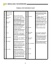
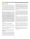
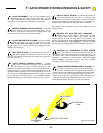
PRESETTING THE MOTOR OVERLOAD
SENSITIVITY
The HDSWG 1000 is shipped from the Factory with the overload
setting at its most sensitive setting. During the initial check out
phase, it will be necessary to adjust the sensitivity to prevent inherent
overloads from gate friction and other gate anomalies. See
Figurez19. Adjust the "OVERLOAD" potentiometer approximately
1/4 turn clockwise. Note! Turning the potentiometer clockwise
decreases sensitivity. Turning the potentiometer counterclockwise
increases sensitivity.
WARNING: THE OVERLOAD POTENTIOMETER MUST
BE SET MORE PRECISELY PRIOR TO COMPLETING THE
HDSWG 1000 INSTALLATION
. (See, FINAL SETTING OF
THE MOTOR OVERLOAD SENSITIVITY)
SETTING THE SWITCH SELECTABLE OPTIONS
The switch selectable options are located on the Logic board. The
board must be removed before the switch can be set. (BE SURE
THAT THE POWER IS OFF BEFORE REMOVING THE LOGIC
BOARD. The boards are keyed with a slot to prevent accidental
incorrect insertion.)
OVERLOAD MODE
The mode of operation for the HDSWG 1000 overload condition is
set at the factory
The HDSWG 1000 will stop when OPENING
and will stop when
CLOSING,
when an overload is detected by the HDSWG 1000
overload function.
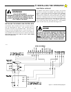
WARNING!
RISK OF ELECTROCUTION
DO NOT BEGIN TO SET THE FOLLOWING
ADJUSTMENTS UNTIL THE POWER IS TURNED
OFF AT THE HDSWG 1000 CONTROL BOX
104896
Figure 19: Switch Selectable
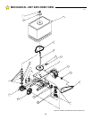
TIMER
MOTOR
OVERLOAD
UPPER LIMIT
SWITCH
LOWER LIMIT
SWITCH
SET SCREW
LOWER LIMIT
CAM
LOWER
LIMIT CAM
CLAMPING
NUT
UPPER
LIMIT CAM
CLAMPING
NUT
UPPER
LIMIT
CAM
106304
Figure 18: Limit Switches
D:
STARTING THE OPERATOR