


12
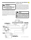
CONNECTING THE AC WIRING
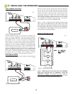
115 VOLT INSTALLATIONS:
Starting at the HDSWG 1000 4 x 4 handy box proceed as follows:
1. The BLACK
wire attaches to the 115 VAC HOT wire, normally
black.
2. The WHITE
wire attaches to the 115 VAC NEUTRAL wire,
normally white.
3. The GREEN
wire attaches to the GROUND wire, normally green.
230 VOLT INSTALLATIONS:
Note: in 230 VAC wiring systems, there will be two "HOT" wires,
normally a red and a black wire. If there is a white wire, typically it
will be a neutral wire. Starting at the HDSWG 1000 4 x 4 handy
box, proceed as follows:
1. The BLACK
wire attaches to one of the 230 VAC HOT wires,
normally black.
2. The RED
wire attaches to the other 230 VAC HOT wire, normally
red.
3. The GREEN
wire attaches to the GROUND wire, normally green.
PROPER OPERATION OF THE SURGE PROTECTOR
MOUNTED ON THE HDSWG 1000 BACKPLANE BOARD
DEPENDS UPON A SOLID GROUND. ALSO, UL LISTING
REQUIRES THAT THE HDSWG 1000
FRAME BE GROUNDED.
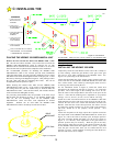
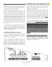
ADDITIONAL LIGHTNING PROTECTION
For those areas where a high probability of ground lightning strikes
exists (Florida, Georgia, etc,) additional lightning protection should
be installed in the HDSWG 1000. Although it may not be possible to
protect against all strikes, additional protection will substantially
reduce the occurrence of lightning damage. Allstar's lightning data
indicates that the most strikes enter the HDSWG 1000 through the
power lines. Effective protection requires that the surge current from
the lightning strike be shunted to ground. This must be done without
raising the potential of the circuitry in the HDSWG 1000, with
respect to ground, to the levels that will damage the solid state
circuitry. Lightning strikes generate enormous currents for very
short periods of time. Unfortunately, the period of time is long
enough to damage solid state components and many times, other
components. The key to success is a very low resistance path from
the surge protector to ground for these currents in addition to a surge
protector that will act fast enough to protect the solid state circuity.
Several manufacturers offer suitable surge protectors.
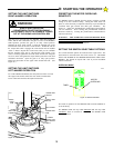
CONNECTING THE MECHANICAL UNIT TO THE
CONTROL BOX
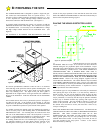
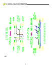
It will be necessary to run two conduits from the Control Box to the
Mechanical Unit. One will be used for the A-C power lines and
another for the low voltage, class 2 wiring. See Figure 8. There are
cutouts on the bottom of the Control Box to accept these two
conduits.
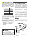
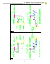
Note the different wiring configurations for right-hand
installations and left-hand installations (see Figure 12, page 13).
For proper operation, the limits and motor must be wired as shown.
BI-PARTING WIRING
For a Bi-Parting installation, an additional two conduits must be
installed between the First Mechanical Unit and the Second
Mechanical Unit. (See Figure 8, page 8.) For a Bi-Parting
installation, one operator must be a Left Hand unit and the other a
Right Hand unit.
The two motors of the Bi-Parting HDSWG 1000's will be wired in
parallel. BOTH
motors will run until both are shut off. If the two
gate leafs do not open exactly the same amount, then the first gate
leaf to reach it's open position will have to be held (or mechanically
stopped) in that positon until the second gate reaches its open
position. Now, both motors can be turned off. The stop for the first
gate can be installed externally or the HDSWG 1000 internal Stop
Pall mounted on the large output drive sprocket of the HDSWG 1000
may be used.
WARNING!
RISK OF ELECTROCUTION
DO NOT BEGIN THE ELECTRICAL CONNECTION
PROCEDURES UNTIL THE POWER IS TURNED
OFF AT THE CIRCUIT BREAKER
C:
INSTALLING THE OPERATOR
WARNING!
TO REDUCE THE RISK OF DAMAGE DUE TO
LIGHTNING, ENSURE A SOLID GROUND FROM
THE HDSWG 1000 GROUND WIRE IN THE
SERVICE ENTRANCE 2 x 4 HANDY BOX TO THE
ELECTRICAL SERVICE GROUND OR TO A
EARTH GROUND STAKE NEAR THE HDSWG