


22
MAXIMUM RUN TIMER
The HDSWG 1000 is equipped with a Maximum Run Timer that is
Factory set to turn the HDSWG 1000 OFF if a Limit Switch
command is not received within 45 Seconds after a Command to
Open or Close is given. The purpose of the Maximum Run Timer is
to turn off the HDSWG 1000 if the gate should become jammed
when opening or closing. In this case, the Limit Switch will not be
activated. Should this occur, the Torque Limiter will slip and the
pads will be worn out prematurely. The Maximum Run Timer will
prevent this by turning OFF the HDSWG 1000. Once the
obstruction is removed, any command will reactive the HDSWG
1000.
WHEN CHECKING OPERATION OF THE LIMIT
SWITCHES, BE CERTAIN THE LIMIT SWITCH IS
TURNING OFF THE MOTOR AND NOT THE
MAXIMUM RUN TIMER. SHOULD THE GATE REACH
THE OPEN OR CLOSED POSITION AND THE
RESPECTIVE LIMIT SWITCH LIGHT DOES NOT
COME ON BUT THE MOTOR STOPS RUNNING, THEN
THE MAXIMUM RUN TIMER IS TURNING OFF THE
MOTOR. SINCE THE NORMAL OPENING AND
CLOSING TIME IS APPROXIMATELY 15 SECONDS,
RESPECTIVELY, TURNING THE HDSWG 1000 OFF
BY THE MAXIMUM RUN TIMER WILL CAUSE THE
TORQUE LIMITER TO SLIP FOR APPROXIMATELY
30 SECONDS EACH TIME THE GATE IS OPERATED.
THE TORQUE LIMITER PADS ARE NOT CAPABLE
OF LONG LIFE UNDER THESE CONDITIONS.
PREMATURE WEAR WILL OCCUR AND FREQUENT
ADJUSTMENT OF THE TORQUE LIMITER WILL BE
NECESSARY.
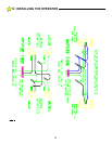
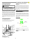
FINAL SETTING OF THE CLOSE TIMER
To alter the amount of time that the close timer will hold the gate
open, adjust the timer potentiometer located on the Logic Board. See
Figure 19.
The Close Timer is adjustable from 0 to approximately 45 seconds.
Turning the potentiometer clockwise increases the delay; turning it
counterclockwise decreases the delay.
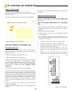
FINAL SETTING OF THE MOTOR OVERLOAD
SENSITIVITY
The motor overload sensitivity was preset before turning on the main
power to prevent the operator from "self-tripping" during the
preliminary adjustment period. NOTE: The HDSWG 1000 is
shipped from the factory with the OVERLOAD option set to stop the
gate in the opening and closing direction if an overload is detected.
Start from the closed gate position and give the HDSWG 1000 an
open command. As the gate is opening, adjust the OVERLOAD
potentiometer in the counterclockwise direction until the
OVERLOAD SENSOR lamp blinks and the gate stops. Adjust the
OVERLOAD potentiometer a very small amount in the clockwise
direction. Give the HDSWG 1000 an open command and observe
the OVERLOAD SENSOR lamp and the Gate. If the light blinks
and the gate stops, again turn the OVERLOAD potentiometer a slight
amount in the clockwise direction. Repeat this process until the gate
will open without the OVERLOAD tripping and with the
OVERLOAD potentiometer in the most counterclockwise direction.
(Make sure the gate swings easily and there are no obstructions in the
path of the gate.)
When you are satisfied that you have the best setting, test this setting
by striking the gate a sharp blow with the palm of your hand when
the gate is closing. The OVERLOAD should respond immediately to
your blow. If the Torque Limiter slips before the overload is
detected, the Torque Limiter will need to be tightened. The purpose
of the Torque Limiter is to protect the mechanical components of the
HDSWG 1000 (primarily the Gear Box). The Torque Limiter should
be adjusted so that the OVERLOAD will be activited before slippage
occurs.
IMPORTANT ! THE OVERLOAD POTENTIOMETER
MUST BE ADJUSTED TO THE MOST SENSITIVE
POSITION POSSIBLE WITHOUT CAUSING "SELF-
TRIPPING" DUE TO THE GATE'S INHERENT FRICTION
OR TO VARIATIONS IN THE GATE HINGE. TRY
ADJUSTING THE POTENTIOMETER SEVERAL TIMES
BY SMALL INCREMENTS, TESTING THE OVERLOAD
BY STRIKING THE GATE WITH YOUR PALM IN BOTH
DIRECTIONS OF TRAVEL. REPEAT THIS TEST UNTIL
YOU ARE SATISFIED YOU HAVE THE MOST
SENSITIVE SETTING OF THE POTENTIOMETER.
Disconnect the crank arm from the output shaft to permit re-
installation of the cover on the mechanical unit. Install the operator
cover and secure it to the frame with (2) 1/4-20 hex bolts.
Remember to re-install the rain seal on the output shaft. Re-connect
the gate arm on the HDSWG 1000 and secure it with the padlock
provided. Complete the installation by replacing the cover on the
Control box.
Review the Installation Notes in Section A of this manual and
describe the gate system operation to the end user. Review the Gate
Operator System Operation and Safety Guide in Section F of this
manual with the end user.
D:
STARTING THE OPERATOR