


23
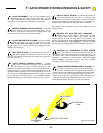
You are now ready to install and connect the ancillary
equipment. INSTALLATION STEPS DETAILED IN
SECTIONS A, B, C AND D MUST BE COMPLETE
BEFORE PROCEEDING.
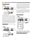
1. Vehicle Detectors:
If a Vehicle Detector (Reversing Loop) is to be a part of this
installation, start with this first. Connect the Vehicle
Detector to AC power and the Loop in accordance with the
Manufacturer's instructions and the information contained in
this manual. Do not connect to the terminal strip of the
HDSWG 1000 at this time. Test the Vehicle Detector
independently using the presense lamp on the front panel of
the detector and a metal plate over the loop. When you are
satisfied that the Detector is working properly, connect the
output wires to the "REVERSING" terminal on the terminal
strip in the Control Box.
Give the gate an open command and allow the Timer to
Close to start the gate to close. Place the metal plate over
the Loop and observe that the "REVERSING" light comes
ON and the gate reopens.
2. Shadow Loop:
WHEN A SHADOW LOOP IS NECESSARY, THE HDSWG
1000 MUST BE ORDERED WITH A SPECIAL DOUBLE
POLE LIMIT SWITCH FOR THE OPEN LIMIT SWITCH.
The Vehicle Detector relay control signal must be routed
through the normally open contacts of the second switch
contacts of the Double Pole Open Limit Switch. When the
gate is in the fully open position, this contact will close the
circuit of the Vehicle Detector to the HDSWG 1000 and
prevent the gate from closing when a vehicle is over the
Shadow Loop. When the gate is closing or opening, this
contact of the Limit Switch is open and the Vehicle Detector
signal path is broken.
If a "Shadow" loop is to be installed, connect the output
wires of this Detector to the "HOLD" open terminal. Place
the metal plate over the Shadow loop. Give the gate an open
command. Note that the gate reaches the fully open
position, that the Hold Open light is ON and that the gate
does not close. Leave the metal plate on the loop for at least
one minute. The gate should not close. Remove the metal
plate from the loop and observe that the gate closes.
3. Free Exit:
If a "FREE EXIT" Detector is installed, connect the output wires of
this Detector to the HOLD OPEN Terminal. (It is acceptable to have
more than one device connected to the same Terminal.) Place the
metal plate over the FREE EXIT LOOP and observe that the HOLD
OPEN lamp is ON and the gate opens to the fully open position.
Leave the metal plate on the loop for at least one minute. Observe
that the gate does not close. Remove the plate from the Loop and
observe that the gate closes. (Some Vehicle Detectors will "tune out"
a constant obstruction to the loop after 15 to 30 minutes.)
4. Installing other entry devices:
After you are satisfied that all the loops are functioning properly,
proceed with the installation of the additional devices, such as a
Radio Receiver, Telephone Entry or Key Pad. Connect the Radio
Receiver to the Radio Terminal. Observe the precautions regarding
radio receivers described on page 15. Other entry devices MUST be
connected to the PULSE terminal.
5. Installing a Magnetic Lock:
The HDSWG 1000 is wired to supply 24 Volts DC to a Magnetic
Lock. The Lock will have two wires that are to be connected
between Terminals #1 and #2 on the Terminal strip in the Control
Box. These terminals are marked LOCK. The maximum current
that can be supplied is 1 AMP. Therefore, the "resistance" of the
Magnetic Lock between it's terminals must measure more than 30
Ohms. (Most Magnetic Locks have a resistance of 100 ohms or
greater.) When the gate is in the closed position, the LOCK light on
the Panel in the Control Box must be ON. (Note, the Allstar MARK
I uses the same Logic Board as the HDSWG 1000, except for the
connection to the LOCK circuit. If the LOCK light is not lighted but
comes on when the gate is opening or closing, a MARK I Logic
Board has been accidently installed in your HDSWG 1000. It must
be replaced with HDSWG 1000 BOARD. The HDSWG 1000 Logic
Board has a small board mounted on the back for the MAXIMUM
RUN TIMER.)
The Magnetic Lock will be released by the HDSWG 1000 about 100
milliseconds prior to giving the gate an open Command. This time
delay is to allow the magnetic field in the Magnetic Lock to decay
and release the Lock prior to starting the gate. If the gate does not
open and it appears that the Magnetic Lock is not releasing promptly,
put a 1000 ohm 1 watt resistor across Terminals 1 and 2 on the
Terminal Strip.
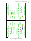
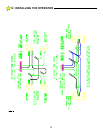
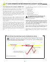
E:
INSTALLATION NOTES FOR AUXILIARY EQUIPMENT