


18
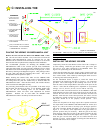
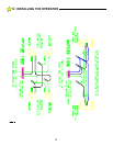
# NAME
DESCRIPTION
1 LOCK SOLENOID
2 LOCK SOLENOID
3 COMMON
One of (2) board commons
provided on the terminal strip
4 CLOSE LIMIT
SWITCH
Used to configure right hand/left
hand operation — See P. 13, Fig
11, Limit Switch Wires.
NOTE: Ensure that wire to terminal 4
is same color as wire to terminal 14.
5 OPEN LIMIT
SWITCH
Used to configure right hand/left
hand operation — See P. 13, Fig
11, Limit Switch Wires.
NOTE: Ensure that wire to terminal 5
is same color as wire to terminal 15.
6 STOP
Continuous or pulsed signal.
Overrides all other signals. Once
activated, the gate will
immediately stop and await a new
command. If the STOP input is
continuously activated, the gate
will not move.
7 CLOSE
Pulsed signal. CLOSE overrides
all other signals except HOLD
OPEN, STOP, and REVERSING.
Once activated, the gate will close
immediately.
8 RADIO OPEN
Pulsed signal. Once activated the
gate will open fully. Activation
while the gate is closing will cause
it to re-open.
9 REVERSING
This input is active only when the
gate is closing or when it’s fully
open and the Close Timer is
operative. All stand-alone vehicle
detectors, photo-eyes and active
edges should be connected here
and to terminals #3 or #13
COMMON. Multiple devices may
be connected in parallel.
10 HOLD OPEN
Continuous or pulsed signal.
Usually used with an external
toggle switch or free exit vehicle
detector. Once activated, the gate
will open fully and remain open
until the HOLD OPEN signal is no
longer present. If the close time is
enabled, the controller will time-
out and close the gate once the
HOLD OPEN input is no longer
active
11 PULSE OPEN
Pulsed signal. Identical in
operation to RADIO OPEN input.
Used for access control devices
such as telephone entry, keypads,
card readers and 3-button
stations.
12 ALTERNATE
Pulsed signal. This input is used
for “COMMAND OPEN/
COMMAND CLOSE” applications.
The 1st signal will cause the gate
to begin opening. A 2nd signal
received during the open cycle will
stop the gate immediately. A 3rd
signal will close the gate. Connect
appropriate access control device
to this terminal and #3 or #13
COMMON. Disable the Close
Timer.
13 COMMON
Second of (2) board commons
provided on the terminal strip.
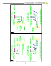
14 MOTOR RUN
WINDING
Used to configure right hand/left
hand operation — See Section C.
Figs. 11 & 12, Motor Control
Wires.
NOTE: Ensure that wire to terminal 14
is same color as wire to terminal 4.
15 MOTOR RUN
WINDING
Used to configure right hand/left
hand operation — See Section C,
Figs. 11 & 12. Motor Control
Wires
NOTE: Ensure that wire to terminal 15
is same color as wire to terminal 5
16 MOTOR COMMON
Center tap for motor run windings
17 AC INPUT
18 AC INPUT
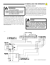
TERMINAL STRIP REFERENCE CHART
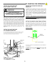
C:
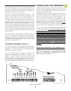
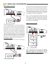
INSTALLING THE OPERATOR